Auxiliary connector and pinouts (j9), 4 auxiliary connector and pinouts (j9) – Comtech EF Data C5 User Manual
Page 123

C5/K1/K3 Integrated Satellite Terminal System
Installation
Rev. 0
3–27
3.4.4
Auxiliary Connector and Pinouts (J9)
AUX connection is a 9-pin female D connector (J9) located on the rear panel of the
modem. Screw locks are provided for mechanical security on the mating connector.
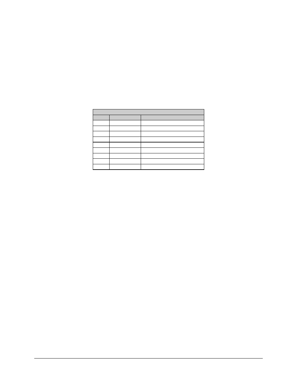
Refer to Table 3-9 for pinout information
Table 3-9. AUX Connector and Pinouts (J9)
Pinout
Pin #
Name
Function
1
SAT_CLK-
SATELLITE CLOCK -
2
NC
NO CONNECTION
3
SAT_CLK+
SATELLITE CLOCK +
4
MDFLTTTL
TRANSMITTER TTL FAULT
5
GND
GROUND
6
RX_Q
RX Q Channel Eye
7
DMDFLTTL
RECEIVER TTL Fault
8
RX _I
RX I Channel Eye
9
AGC
AGC Output
