Figure 4-21. if loopback, Figure 4-22. baseband loopback – Comtech EF Data C5 User Manual
Page 192

Operation
C5/K1/K3 Integrated Satellite Terminal System
4–66
Rev. 0
CUSTOMER
DATA
REMOTE SERIAL
INTERFACE
FAULT INDICATORS
IESS-308-2
INTERFACE
ENCODER/
MODULATOR
TRANSMIT RF
EQUIPMENT
MICRO-
COMPUTER
POWER
SUPPLY
RECEIVE RF
EQUIPMENT
AC POWER
ANTENNA
DEMODULATOR/
DECODER
IDU
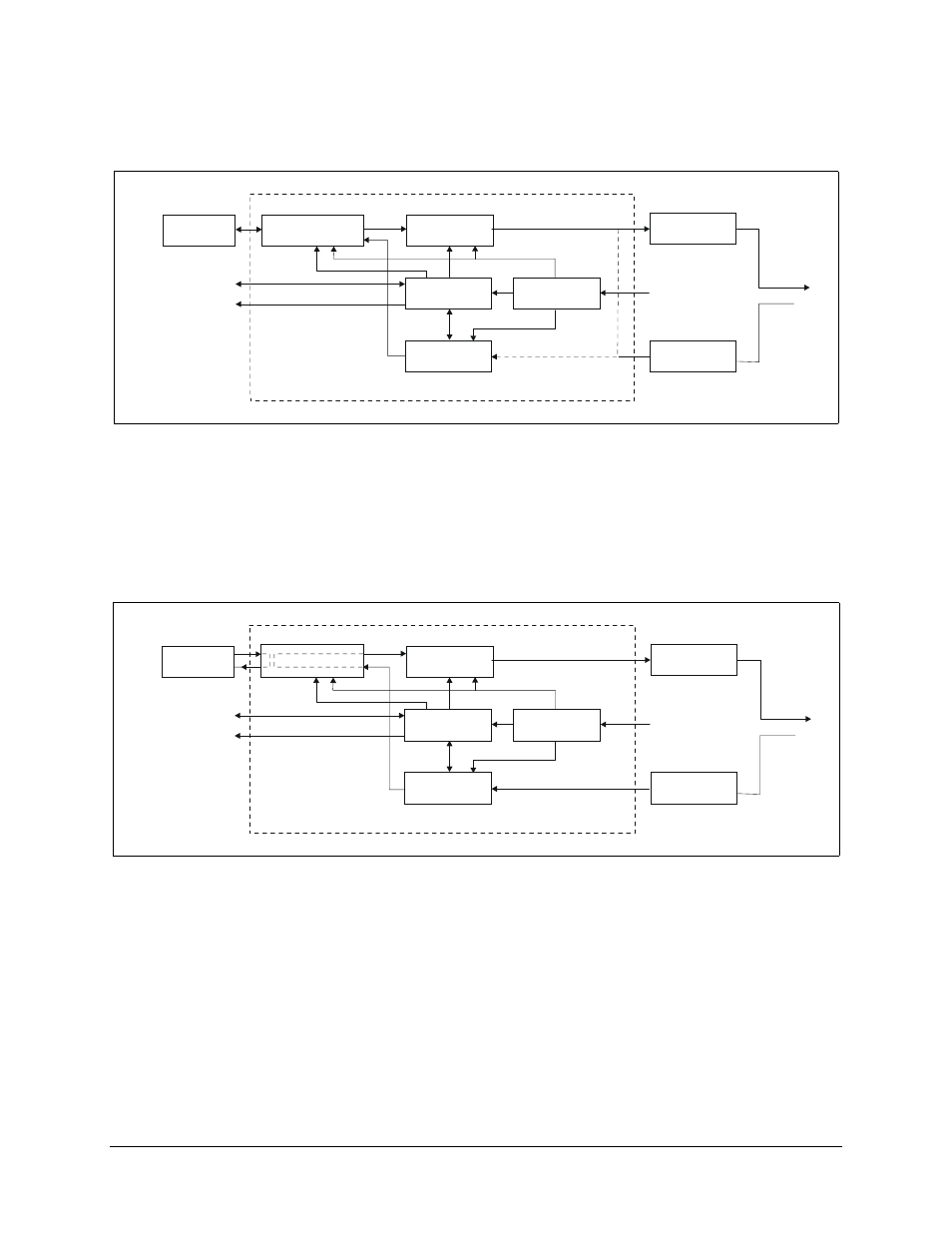
Figure 4-21. IF Loopback
Note: When IF loopback is turned on, the demodulator is looped back to the modulator inside the modem and the demodulator is programmed to
the same frequency as the modulator. This test mode will verify the operation of the modem. When IF loopback is turned off, the demodulator is
programmed back to the previous frequency and is reconnected to the IF input.
CUSTOMER
DATA
REMOTE SERIAL
INTERFACE
FAULT INDICATORS
INTERFACE
ENCODER/
MODULATOR
TRANSMIT RF
EQUIPMENT
MICRO-
COMPUTER
POWER
SUPPLY
RECEIVE RF
EQUIPMENT
AC POWER
ANTENNA
DEMODULATOR/
DECODER
IDU
Figure 4-22. Baseband Loopback
Note: When baseband loopback is turned on, data is looped back on the customer side of the interface. This is a bi-directional loopback of the
baseband data. This test mode will verify the customer equipment and cabling between the modem and the customer equipment.
