Display enable, Table 41 - display enable settings, Time & date – Rockwell Automation 825-P Modular Protection System for Motors User Manual User Manual
Page 94: Ground current, Current imbalanc, Frequency, Therm cap used, Rtd temperature, Voltage imbalanc, Power
94
Rockwell Automation Publication 825-UM004D-EN-P - November 2012
Chapter 6 Configuring Protection & Logic Functions
The LCD TIMEOUT indicates the duration of inactivity before the LCD
backlight will extinguish, the Access Level will be automatically reset and the
present function will be automatically terminated. Use the front panel LCD
Timeout setting as a security measure. If the display is within an Access Level 2
function, such as the relay setting entry, the function is automatically terminated
(without saving changes) after inactivity for this length of time. The front-panel
display returns to the default display (see Table 41 for the default rotating display
settings).
If you prefer to disable the front-panel timeout function during relay testing, set
the LCD Timeout equal to 0 minutes. Use the front panel LCD Contrast setting
to adjust the contrast of the liquid crystal display.
Display Enable
The relay default front-panel rotating display shows unit identifiers (see Table 7)
and magnitudes of measured phase currents and, if included, phase-to-phase
voltages.
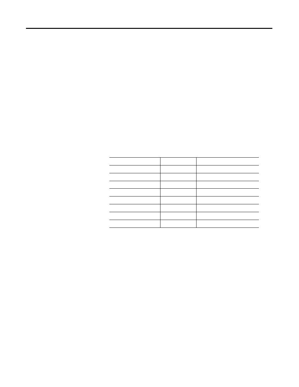
The Display Enable settings give you the option to add quantities listed in
Table 41 to the default display. When you select Y for a quantity, it is added
to the rotating display.
Voltage Imbalance and Power displays require the voltage input option. When
the relay is equipped with external RTD inputs and the Display Enable RTD
Temperature setting equals Y, the relay displays the temperatures of the hottest
winding, bearing, and other RTDs, plus the ambient temperature.
Table 41 - Display Enable Settings
Setting Prompt
Setting Range
Factory Default
TIME & DATE
Y, N
N
GROUND CURRENT
Y, N
N
CURRENT IMBALANC
Y, N
N
FREQUENCY
Y, N
N
THERM CAP USED
Y, N
N
RTD TEMPERATURE
Y, N
N
VOLTAGE IMBALANC
Y, N
N
POWER
Y, N
N