Voltage transformer (vt) configuration settings, Basic motor protection – Rockwell Automation 825-P Modular Protection System for Motors User Manual User Manual
Page 69
Rockwell Automation Publication 825-UM004D-EN-P - November 2012
69
Configuring Protection & Logic Functions Chapter 6
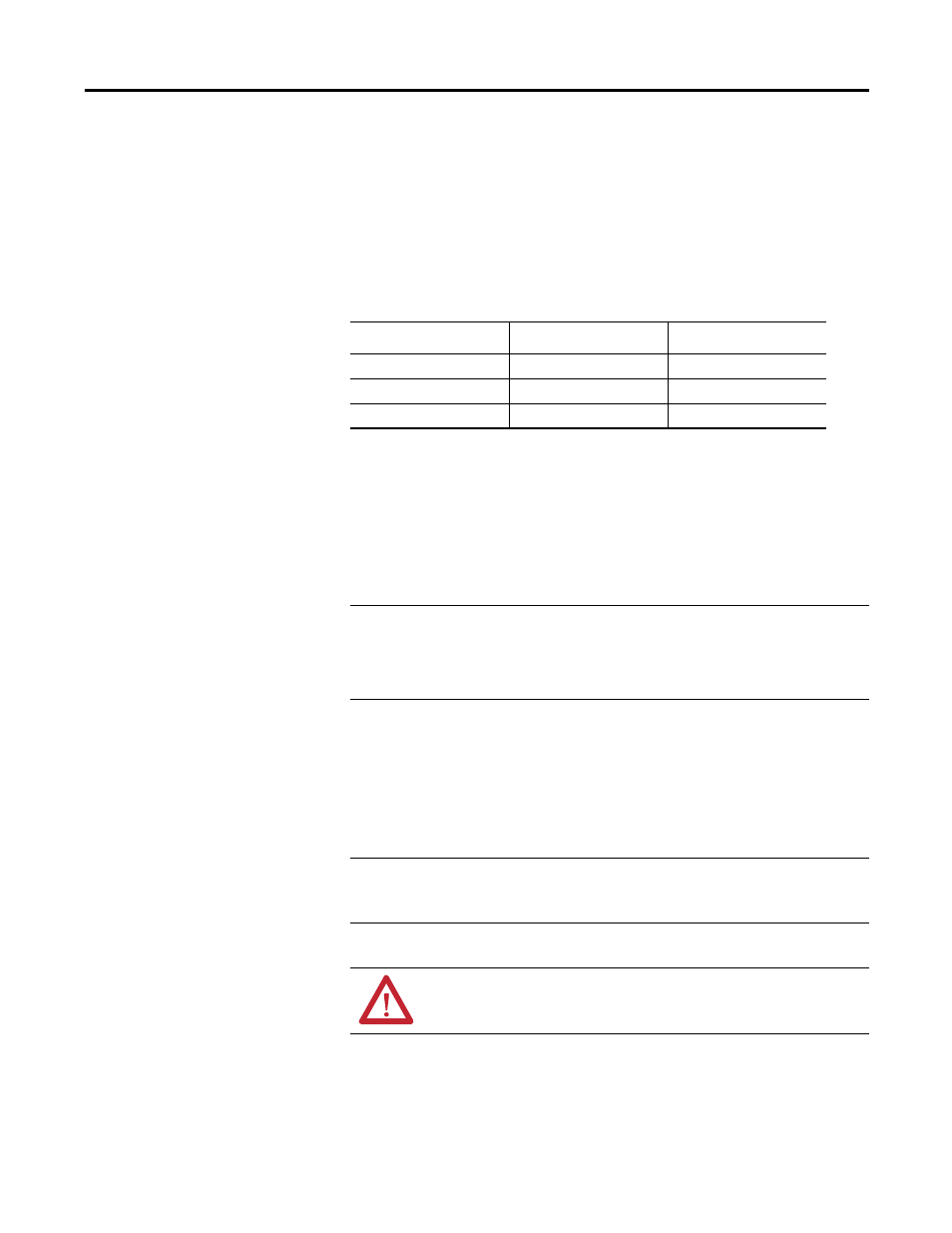
Voltage Transformer (VT) Configuration Settings
Relays that are not equipped with phase voltage inputs will hide these settings
and disable voltage-based protection and metering functions.
Table 10 shows voltage settings for relay models with optional voltage inputs.
Table 10 - CT Configuration and Full Load Current Settings
These settings configure the optional relay voltage inputs to correctly measure
and scale the voltage signals. Calculate the Phase VT Ratio by dividing the
primary rating by the secondary rating.
When phase-to-phase PTs are connected to the relay, set XFMR Connection
equal to Delta. When phase-to-neutral PTs are connected to the relay, set XFMR
Connection equal to Wye.
Basic Motor Protection
Setting Prompt
Setting Range
Factory Default
PHASE VT RATIO
1…250
34.65
LINE VOLTAGE
100…30000V
4160
XFMR CONNECTION
Delta
Wye Delta
NOTE:
The line voltage setting is in primary volts.
EXAMPLE
Phase VT Ratio Setting Calculation:
Consider a Phase VT Ratio Setting calculation, consider a 4000V motor application
where 4200:120V rated voltage transformers (connected in open delta) are used.
Set the VT Ratio := 4200/120 := 35 and DELTA_Y := Delta
IMPORTANT
Settings associated with options or accessories (converter module, voltage input card,
expansion I/O card, RTD scanner) require their installation or connection prior to being
made available for configuration.
ATTENTION: Configuration of protection elements is not complete until the elements
are assigned to the trip or auxiliary relays. Refer to I/O Assignments for instructions.