Table 12 - motor codes, 4 and up – Rockwell Automation 825-P Modular Protection System for Motors User Manual User Manual
Page 72
72
Rockwell Automation Publication 825-UM004D-EN-P - November 2012
Chapter 6 Configuring Protection & Logic Functions
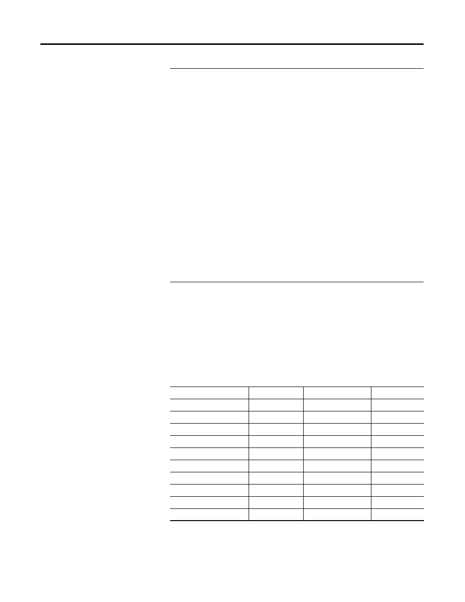
If the Locked Rotor Ampere rating for the motor is unknown, but the motor
has a Motor Code designation, use the following table as provided by NEMA
(National Electrical Manufacturer Association) to determine the locked rotor
ampere value.
➊
Locked kVA per horsepower range includes the lower figure up to, but not including, the higher figure; e.g., 3.14 is designated by letter
A and 3.15 is designated by letter B.
EXAMPLE
Thermal Element Setting
A 4000V 600 Hp motor is protected using the 825-P Thermal Overload Element. Motor
data sheet includes the following:
•
Rated Horsepower = 600 Hp
•
Rated Voltage = 4000V
•
Rated Full Load Current = 80 A
•
Rated Locked Rotor Amps = 480 A
•
Safe Stall Time at 100% Volts:
•
Cold = 18 seconds
•
Hot = 15 seconds
•
Service Factor = 1.2
Phase current transformers with 100:5 A rating and the MCM20 module are selected
for application. 825-P settings for application are calculated as shown below:
•
Current Transformer Ratio: := 100/5 := 20
•
Full Load Amps (Ie): := 80 A primary
•
Service Factor: := 1.2
•
Locked Rotor Amps: := 480.0/80.0 := 6.0 x Ie
•
Hot Locked Rotor Time: := 15.0 seconds
•
Run state time constant: := Auto
NOTE:
To prevent nuisance tripping from occurring when a motor operates at the rated service
factor, set Service Factor to 0.01 plus the motor nameplate value.
Table 12 - Motor Codes
Letter Designation
kVA/HP
➊
Letter Designation
kVA/HP
➊
A
0…3.15
L
9.0…10.0
B
3.15…3.55
M
10.0…11.2
C
3.55…4.0
N
11.2…12.5
D
4.0…4.5
P
12.5…14.0
E
4.5…5.0
R
14.0…16.0
F
5.0…5.6
S
16.0…18.0
G
5.6…6.3
T
18.0…20.0
H
6.3…7.1
U
20.0…22.4
J
7.1…8.0
V
22.4 and up
K
8.0…9.0