Table 16 - ground-fault residual settings – Rockwell Automation 825-P Modular Protection System for Motors User Manual User Manual
Page 76
76
Rockwell Automation Publication 825-UM004D-EN-P - November 2012
Chapter 6 Configuring Protection & Logic Functions
When a ground-fault CT is connected to the 825-P, as in Figure 14, use the CB
ground-fault element to detect motor ground faults. Calculate the Trip and Warn
level settings based on the available ground fault current and the CB CT ratio.
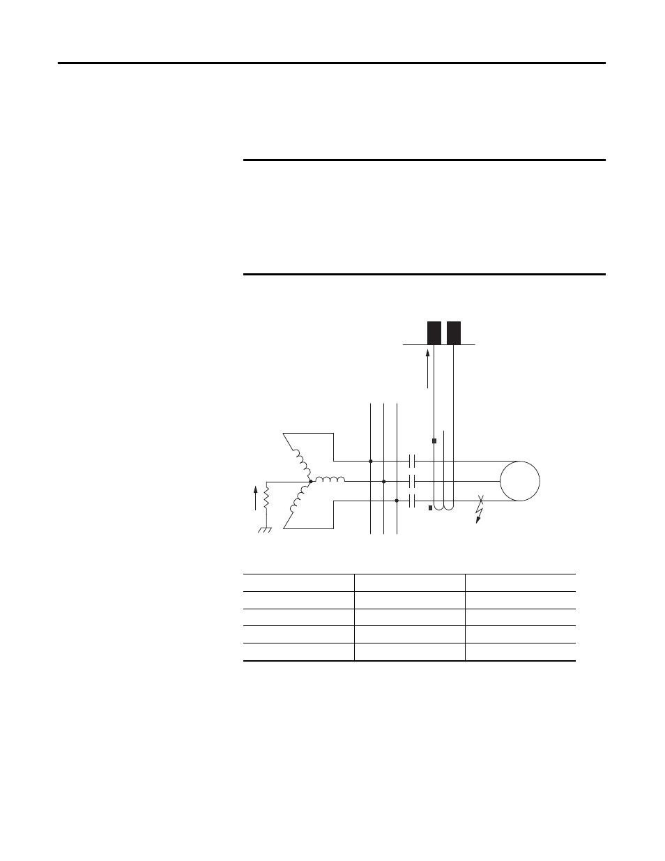
Figure 29 - Ground-Fault Protection Using Core Balance CT
For solidly grounded systems, the residual ground fault elements can be used.
EXAMPLE
Ground-Fault CB CT Application
A resistance-grounded transformer limits current for motor or cable ground faults.
The resistor is sized to limit current to 10 A primary. The three motor leads are passed
through the window of a 10:1 core balance CT. The CT secondary is connected to 825-P
CBCT input terminals, as shown in Figure 29. Setting the core balance CT Ratio equal to
10 and Ground Fault Trip Level equal to 5 A with 0.10 second time delay ensures that
the element quickly detects and trips for motor ground faults, but prevents faulty
operation due to unequal breaker or contactor pole closing times.
Table 16 - Ground-Fault Residual Settings
Setting Prompt
Setting Range
Factory Default
GF-RES TRIP LEVL
Off, 0.10…1.00 x
I
e
Off
GF-RES TRIP DLAY
0.00…5.00 s
0.50
GF-RES WARN LEVL
Off, 0.10…1.00 x
I
e
Off
GF-RES WARN DLAY
0.0…120.0 s
10.0
NOTE:
Phase CT ratios are typically higher than CB CT ratios. For this reason, the relay sensitivity to
motor ground faults is less when the residual overcurrent element is used instead of the CB
element. A separate ground fault detection method should be used if a CB CT is not available
in applications where resistance grounding reduces the available ground fault current.
10 A
C-Ground Fault
10 A
1 A
10:1
Window CT
S1
S2
Motor
A B C