Table 58 - message configuration – Rockwell Automation 825-P Modular Protection System for Motors User Manual User Manual
Page 123
Rockwell Automation Publication 825-UM004D-EN-P - November 2012
123
825-PDN DeviceNet Communication Card Chapter 9
CT Ratio. See Table 59, Common Configuration Examples for 825-P Modular
Protection System for additional configurations.
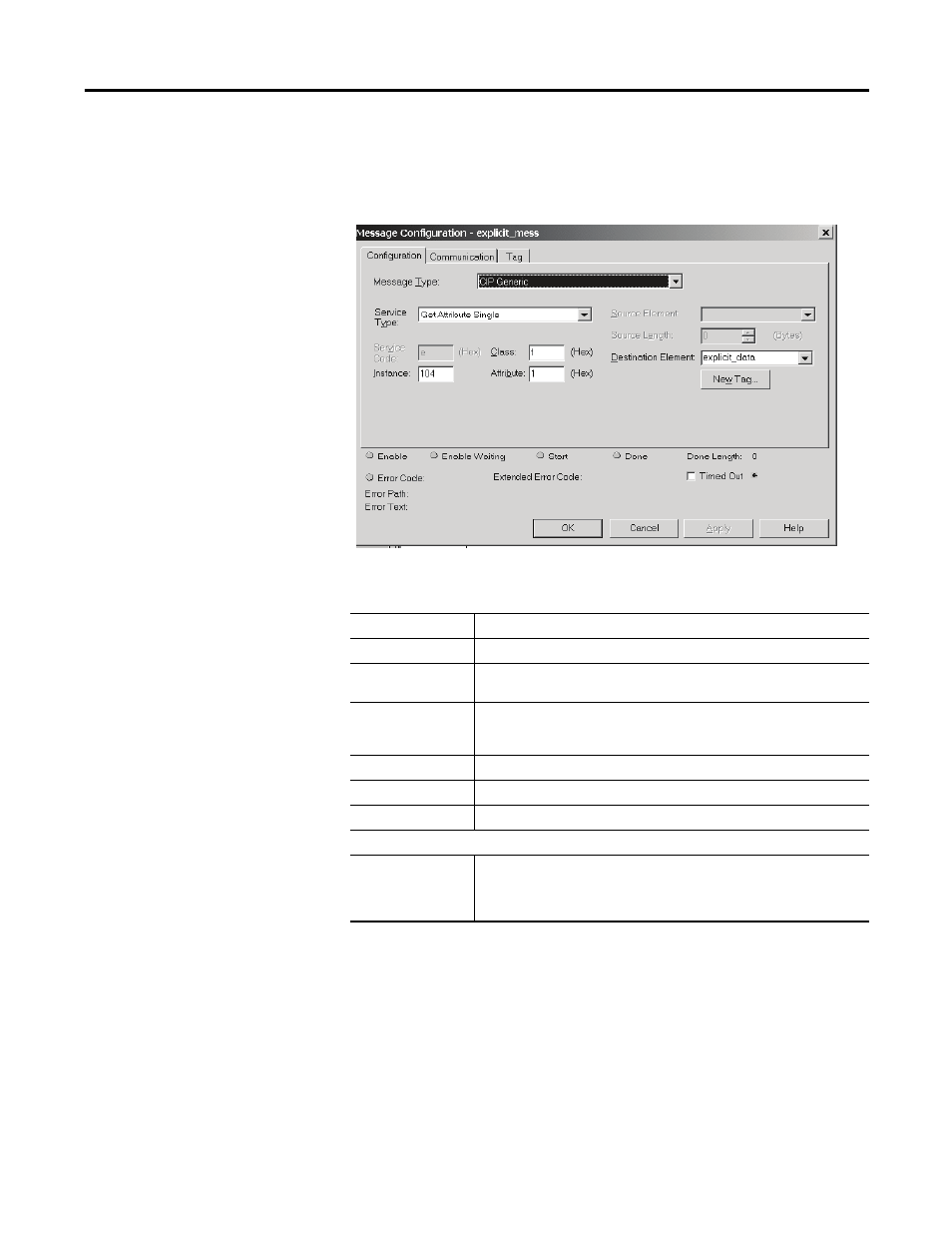
Table 58 - Message Configuration
Table 59 - Description of Message Configuration Fields
Field
Description
Message Type
Select CIP Generic from pull-down menu to configure an explicit message.
Destination
Element
Tag name of the location you are going to place the response information. In this example
a tag was created with the name explicit_data.
Service Type
Pull-down menu has several options, however only the Get Attribute Single is used for this
example. The Class, Instance, and Attribute define the actual information being requested.
Additional configurations of these parameters can be found in Appendix B.
Class
In this example, the value is F.
Instance
In this example, the value is 104.
Attribute
In this example, the value is 1.
After the above information has been entered, click on the communication tab
Path
Path defines the route the message takes to get to the device it is intended for. In this
example the path is Scanner,2,4; where scanner is the name of the 1756-DNB in the rack,
2 represents the DeviceNet port, and 4 represents the physical node address of the 825-P
Modular Protection System.