5 state descriptions, For d – INFICON IC/5 Thin Film Deposition Controller User Manual
Page 82
3 - 30
IP
N 07
4-
23
7A
E
IC/5 Operating Manual
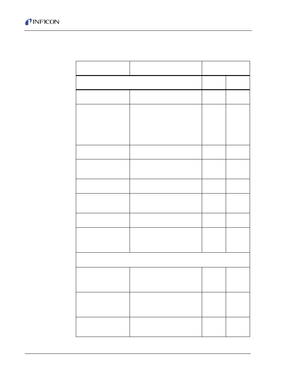
3.5 State Descriptions
Table 3-3 State Descriptions
STATE
CONDITION
RELAY CONTACT
STATUS
NOTE: 1 through 7 are Pre-Deposit states.
Source
Shutter
Sensor
Shutter
1. READY
The IC/5 will accept a START
command
Inactive
Inactive
2. SOURCE SWITCH
Instrument advances to next state
when “turret” input is low, or “turret”
delay has elapsed. If IDLE PWR of
the previous layer using this source
is not equal to zero, power is set to
zero before the crucible position
changes. [Crucible #, Source #]
Inactive
Inactive
3. RISE TIME 1
Source is rising to Soak Power 1
level. [Rise Time 1]
Inactive
Inactive
4. SOAK TIME 1
Source is being maintained at Soak
Power 1 level. [Soak Time 1, Soak
Power 1]
Inactive
Inactive
5. RISE TIME 2
Source is rising to Soak Power 2
level. [Rise Time 2]
Inactive
Inactive
6. SOAK TIME 2
Source is being maintained at Soak
Power 2 level. [Soak Time 2, Soak
Power 2]
Inactive
Active
7. SOAK HOLD 1
SOAK HOLD 2
Source is being maintained at Soak
Power level. [Soak Hold input]
Inactive
Inactive
Inactive
Active
8. SHUTTER DELAY
Rate is being controlled. Advances
to Deposit State once the Source is
in Rate Control within > of 5% or
1A/s. [Shutter Delay ON]
Inactive
Active
NOTE: 9 through 16 are Deposit states.
9. CONTROL DELAY
Constant Power at Soak Power 2.
Startsrate control when the control
delay time elapses. [Control Delay,
Control Delay Time]
Active
Active
10. DEPOSIT
Rate control. [Rate, Final
Thickness, PID COntrol, Process
Gain, Primary Time Constant,
System Dead Time]
Active
Active
11. RATE RAMP TIME 1
Rate control, desired rate
changing. [New Rate 2, Start Ramp
2, Ramp Time 2]
Active
Active