INFICON IC/5 Thin Film Deposition Controller User Manual
Page 63
3 - 11
IP
N 07
4-
23
7A
E
IC/5 Operating Manual
During the OPERATE display, the function keys along the right side of the screen
will function as explained in
.
In addition to the standard operational screen, if the system is configured for
co-deposition, the operational screen will be divided to show information for both
layers. Two options of the co-deposition OPERATE screen are available. One
includes the graph information as shown in
. The other removes the
graph and shows enlarged digital information for Rate, Thickness, and Power. The
format is determined by a parameter in the UTILITY screen. (See
.)
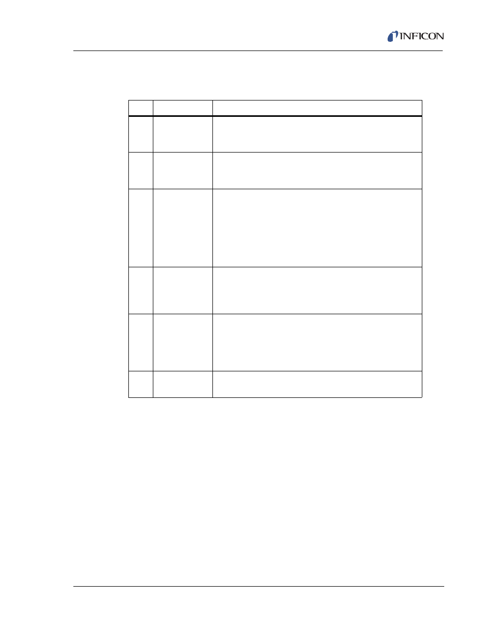
Table 3-2 Operate Display Function Keys
Key Function
Description
F1
ZERO
THICKNESS
To reset to zero both the displayed thickness of the current
layer and the sensor thickness values shown on page 3 of
the Material display, press function key F1.
F2
SENSORS
To access the SENSORS display, (see
) which allows crystal switching and displays sensor
diagnostic information, press function key F2.
F3
MANUAL
To put the layer in manual control, (so that the power level
is controlled by the hand-held controller), press function key
F3. When in manual, the F3 panel reads AUTO, and
pressing it will remove the layer from the manual state and
place it into the DEPOSIT state. See State Descriptions
(
) for a more complete description
of manual operation.
F4
KEY SWITCH 2
(or KEY
SWITCH 1)
When co-depositing two layers (see
), press this
key to change the numeric designators for F1 and F3. The
function key works in toggle fashion between the secondary
(Key Switch 2) and primary (Key Switch 1) layers.
F5
MAIN/DIAG
Press this key while in the READY state to move to the
Maintenance/Diagnostics display. This allows selection of
Source Maintenance or Diagnostics functions for the
Remote communications port, or Cross Talk Calibration.
(See
.)
F6
PROGRAM
To move to the PROGRAM menu, press F6. (See
.)