1 rs-232c serial port – INFICON IC/5 Thin Film Deposition Controller User Manual
Page 147
7 - 5
IP
N 07
4-
23
7A
E
IC/5 Operating Manual
The word format for bit serial lines (RS-232C) is comprised of ten signal bits- eight
data bits, one start bit, one stop bit and no parity. The eight data bits comprise a
byte of information or character whose ASCII value ranges from 0 to 255.
7.5.1 RS-232C Serial Port
RS-232C serial communications are accomplished through an industry standard
9-pin female connector found on the rear panel of the instrument. A mating male
connector is required for attachment of a host interface. The host and instrument
can be separated by up to fifty feet using multiconductor shielded data cable.
The instrument is configured as DCE or Data Communication Equipment.
The following pin assignments should be used when constructing a cable:
The port incorporates hardware flow control via Request to Send / Clear to Send
(RTS/CTS) and Data Terminal Ready / Data Set Ready (DTR/DSR) signaling.
Request To Send (RTS) . . . . . . . . . . The instrument informs the host it is ready to
receive a character by asserting the RTS
signal. It lowers the signal when the receive
buffer is full.
Clear to Send (CTS). . . . . . . . . . . . . The host informs the instrument it is ready to
receive a character by asserting the CTS
signal. The host should lower the signal if its
received buffer becomes full and raise the
signal when it can receive data again. This
signal has an internal pull up in the
instrument. Therefore, if left disconnected
the instrument will assume the host is always
capable of receiving data (no flow control).
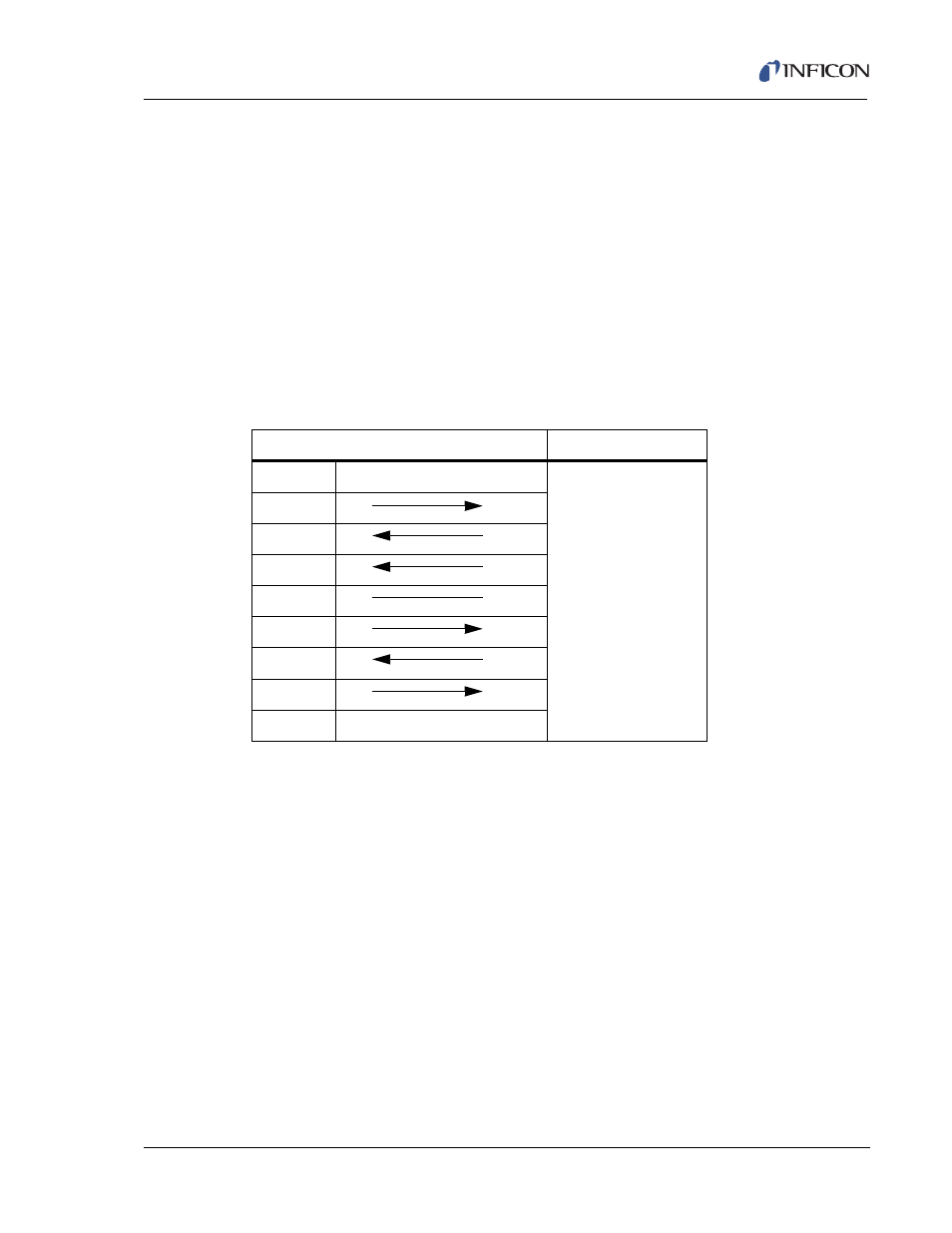
Table 7-2 RS-232C Cable Pin Assignments
IC/5 (9-Pin D-sub)
Host
Pin 1
(Not used)
The 760-406-P1
RS232 Loop-back
connector provided in
the ship kit connects
the following pins:
2 to 3,
4 to 6 and
7 to 8.
Pin 2
TXD
RXD
Pin 3
RXD
TXD
Pin 4
DSR
DTR
Pin 5
GND
GND
Pin 6
DTR
DSR
Pin 7
CTS
RTS
Pin 8
RTS
CTS
Pin 9
GND (Shield)