3 connecting the controller, 1 verifying the correct input voltage – INFICON IC/5 Thin Film Deposition Controller User Manual
Page 240
11 - 8
IP
N 07
4-
23
7A
E
IC/5 Operating Manual
11.3 Connecting the Controller
The operation of the controller depends on the proper connection of power and
signal interfaces to owner equipment and sources.
11.3.1 Verifying the Correct Input Voltage
WARNING - Risk Of Electric Shock
This instrument has line voltage present on the primary
circuits whenever it is plugged into a main power source.
Never remove the covers from the instrument during
normal operation.
There are no operator serviceable items within this
instrument.
Removal of the top or bottom covers must be done only
by a technically qualified person.
In order to comply with accepted safety standards, this
instrument must be installed into a rack or system which
contains a mains switch. This switch must break both
sides of the line when it is open and it must not interfere
with the safety ground.
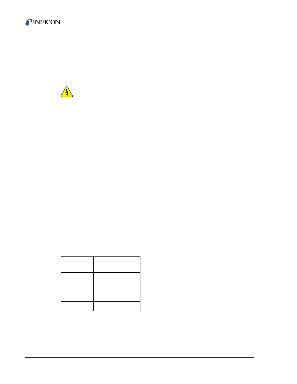
The controller is initially powered by AC line current. The four supported nominal
voltage settings and their acceptable voltage input ranges are shown in
.
One of these nominal voltages has been factory set and that number shows
through the window in the power input module. The line voltage provided in your
facility must be within the voltage range indicated in
for the nominal
setting.
Table 11-2 Supported Nominal Voltage Settings
Nominal
Setting
Acceptable
Input Range
100 V(ac)
85 to 110 V(ac)
120 V(ac)
108 to 132 V(ac)
230 V(ac)
207 to 253 V(ac)
240 V(ac)
204 to 264 V(ac)