4 maintenance/diagnostics display – INFICON IC/5 Thin Film Deposition Controller User Manual
Page 69
3 - 17
IP
N 07
4-
23
7A
E
IC/5 Operating Manual
3.3.4 Maintenance/Diagnostics Display
These displays provide a simple method for system maintenance and diagnostics.
Pressing the MAIN/DIAG function key during the Operate display accesses the
Maintenance/Diagnostics display.
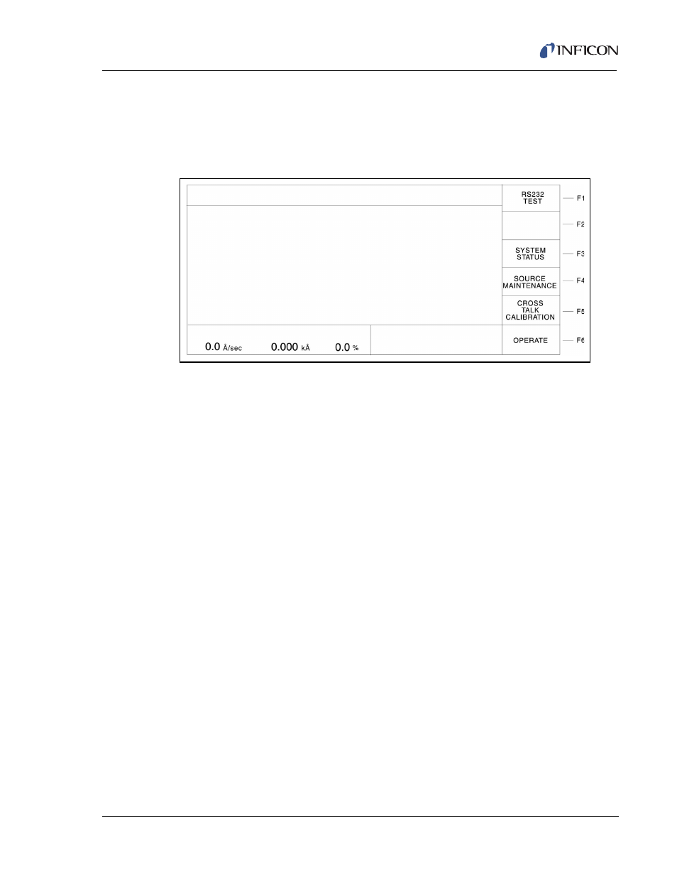
Figure 3-9 Maintenance/Diagnostics Display
3.3.4.1 Function Key Selection Choices for the Maintenance/Diagnostics Display
F1 RS232 TEST
Press function key F1 to initiate the RS-232C COMM PORT self test. Upon
completion of the test, the unit will display a message indicating the test was
successful and the COMM PORT is okay; or the test failed and the COMM
PORT is bad. If the COMM PORT is bad, a reminder message to make certain
the RS-232C loop back connector is installed is displayed.
NOTE: The RS-232C Loop Back connector, IPN 760-406-P1 must be installed
on the IC/5 RS-232C port for the self test to work properly.
F3 SYSTEM STATUS
Press function key F3 to access the SYSTEM STATUS display. The SYSTEM
STATUS display can also be accessed using the MENU TREE.
F4 SOURCE MAINTENANCE
To move to the Source Maintenance display, press function key F4.
F5 CROSS TALK CALIBRATION
To enter the cross talk calibration series of displays, press function key F5.
Cross talk calibration is used in co-deposition applications to correct for
material flux from one source being deposited onto the sensors used to control
the other material’s source. See
for the Cross Talk
Calibration Procedure.
F6 OPERATE
To return to the Operate display, press function key F6.