Rear roller and bushing replacement, To section 11.3.16, “rear, Roller and bushing replacement – Lull 944E-42 Service Manual User Manual
Page 825
11.23
Model 644E-42/944E-42
Rev. 6/04
Transfer Carriage
Note: It is reccomended to replace both bearings at the
same time.
Note: DO NOT apply any grease or anti-seize
compound to bushing or roller pin.
11. Inspect the front roller bearings (15). If they are worn
and visibly shake on the roller pin, replace with new
self-lubricating bearings.
12. Insert roller pin (11), front roller (13) and shims (14)
in their previously labeled positions.
13. Coat the capscrews (7) with Loctite
®
242 (blue).
Replace capscrew (7), washer (8), spacer (9) and
locknut (10) to secure pin on transfer carriage (12).
Torque capscrew to 43 - 78 lb-ft (59 - 106 Nm).
14. Repeat steps 8 through 13 for the other front roller.
15. If the vehicle has dual batteries, connect both
negative battery cables (1 and 2) to both batteries.
Connect the lower negative battery cable (1) to the
negative (-) terminal on the lower battery (3). Swing
the upper battery box (6) in and make sure that the lip
(5) on the upper battery box slides below the knob
(4). Secure in place with the knob (4).
16. Close and lock the engine compartment cover.
17. Inspect rear rollers. (Refer to Section 11.3.12, “Front
18. If required, perform rear rollers shimming. (Refer to
Section 11.3.13, “Front Roller Shimming.”)
11.3.16
Rear Roller and Bushing Replacement
Note: The attachment should remain attached to the
quick attach.
1. Park the vehicle on firm level ground. Place the
travel select lever in the (N) NEUTRAL DETENT
position, engage the parking brake switch and raise
the boom to a horizontal (level) position.
2. Fully retract the boom and fully retract the transfer
carriage. Shut the vehicle OFF.
3. Lift the boom with a hoist to remove pressure off the
front rollers. There should be a gap between the
rollers and the rails.
4. Shut the engine OFF.
5. Place an Accident Prevention Tag on both the
ignition switch and steering wheel, stating that the
vehicle should not be operated. (Refer to Section
1.5, “Accident Prevention Tag Usage.”)
6. Open the engine compartment cover. Allow the
engine, transmission and hydraulic fluid to cool.
7. If the vehicle has dual batteries, disconnect both
negative battery cables (1 and 2) from both
batteries.
To access the lower battery (3), loosen the knob (4)
far enough so that the lip (5) on the upper battery box
clears the knob. Lift up the upper battery box (6) and
swing it out, so that the box clears the hydraulic tank
support bracket, to gain access to the lower negative
battery cable (1). Disconnect the lower negative
battery cable.
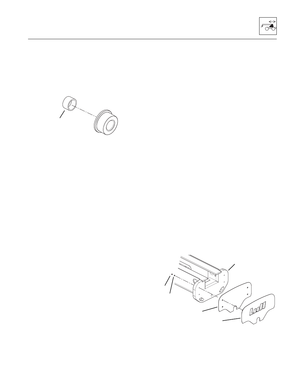
8. Remove locknuts (16), washers (17), Lull logo
plate (18) and black backing (19) from the rear of the
vehicle (20).
MU3210
15
MU1630
16
17
18
19
20