To section 9.14.8, Transmission shift control switch, To section 9.14.9 – Lull 944E-42 Service Manual User Manual
Page 734: Transmission solenoid valves
Electrical System
9.224
Model 644E-42/944E-42
Rev. 6/04
9.14.8
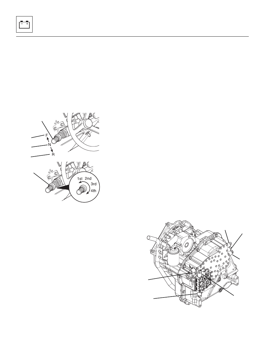
Transmission Shift Control Switch
a. Travel Select Lever
The transmission shift control switch, travel select
lever (1), is located on the left side of the steering column.
The switch has three positions:
FORWARD (F, all the way up) (2),
NEUTRAL DETENT (N, center position) (3), and
REVERSE (R, all the way down) (4).
The switch or lever must be in the NEUTRAL
DETENT (N) (3) position to permit engine starting.
Moving the lever (1) opens and closes electrical contacts
in the switch, allowing electricity to flow to the appropriate
relays and on to the transmission shift solenoids.
Travel selections are changed by grasping the lever,
pulling it toward the steering wheel, then UP or DOWN to
the desired selection, FORWARD (F) (2) or
REVERSE (R) (4).
When the switch is shifted to the REVERSE (R) (4)
position, the back-up alarm will automatically sound.
(Refer to circuit diagrams in Section 9.9, “Transmission
Gear Selection Troubleshooting,” and also, Section
9.14.9, a. “Travel Select Lever and Wiring Harness
Testing.”)
For removal and installation instructions refer to Section
4.3.2, c. “Transmission Travel and Gear Select Lever
Removal,” and Section 4.3.2, d. “Transmission Travel
and Gear Select Lever Installation.”
b. Gear Select Lever
The gear select lever (5) is part of the transmission shift
control switch, travel select lever (1). The lever has a
twist-grip handle with four positions.
The vehicle has four forward and three reverse gears.
First gear is used for the highest torque and pulling
power, and the higher-numbered gears are for increasing
vehicle travel speed.
For removal and installation instructions refer to Section
4.3.2, c. “Transmission Travel and Gear Select Lever
Removal,” and Section 4.3.2, d. “Transmission Travel
and Gear Select Lever Installation.”
9.14.9
Transmission Solenoid Valves
The transmission is shifted via six solenoids. Three
solenoids valves Y1 (6), Y2 (7) and Y3 (8) are located on
the right front corner of the transmission. The remaining
three solenoid valves Y4 (9), Y5 (10) and Y6 (11) are
located on the left front corner of the transmission.
While each 12-volt solenoid coil on the transmission are
the same, the internal wiring to the solenoids is different
and connected so that the various transmission clutches
can be actuated via input from the transmission shift
control switch/travel select lever (1). By placing the
transmission shift control switch/travel select lever (1), in
any given position, a combination of solenoids are
activated, which in turn, engages a set combination of
internal clutches. (Refer to Section 9.14.9, a. “Travel
Select Lever and Wiring Harness Testing,” and Section
9.14.9, b. “Transmission Solenoid Testing.”)
MU3840
1
2
3
4
5
MU3850
6
7
8
9
10
11