Lull 944E-42 Service Manual User Manual
Page 472
Hydraulic System
8.220
Model 644E-42/944E-42
Rev. 6/04
Note: If a white, powdery residue remains on the
threads and parts, clean the residue away with a soft
brass wire brush prior to reassembly, and wipe with
Loctite “T” cleaner before proceeding.
7. Apply Loctite Threadlocker #271 (red) to the
locknut (11). Thread the locknut onto the rod (3) and
torque to 445-515 lb-ft (603-698 Nm). The threads
will deform upon tightening, locking the nut in place.
8. Install the capped T-seal (10) and precision
wearband (9) onto the piston (5).
Note: The T-seal actually consists of four components; a
wide, flexible inner band, the flexible T-seal band itself,
and two supportive split caps that mount on either side of
the “T” itself.
9. Install new oiled o-ring (6), back-up ring (7) and
locking insert (8) onto the head gland (4).
IMPORTANT: When sliding the rod and piston assembly
in the tube, prevent the threaded end of the tube from
damaging the piston (5). Keep the rod centered within
the tube to help prevent binding. Protect the finish on the
rod at all times. Damage to the surface of the rod can
cause seal failure.
10. Carefully insert the rod (3), with all attachments,
straight into the tube (2).
11. Using a pin spanner wrench, thread the head
gland (4) into the tube (2). Torque the head gland to
250-300 lb-ft (339-407 Nm).
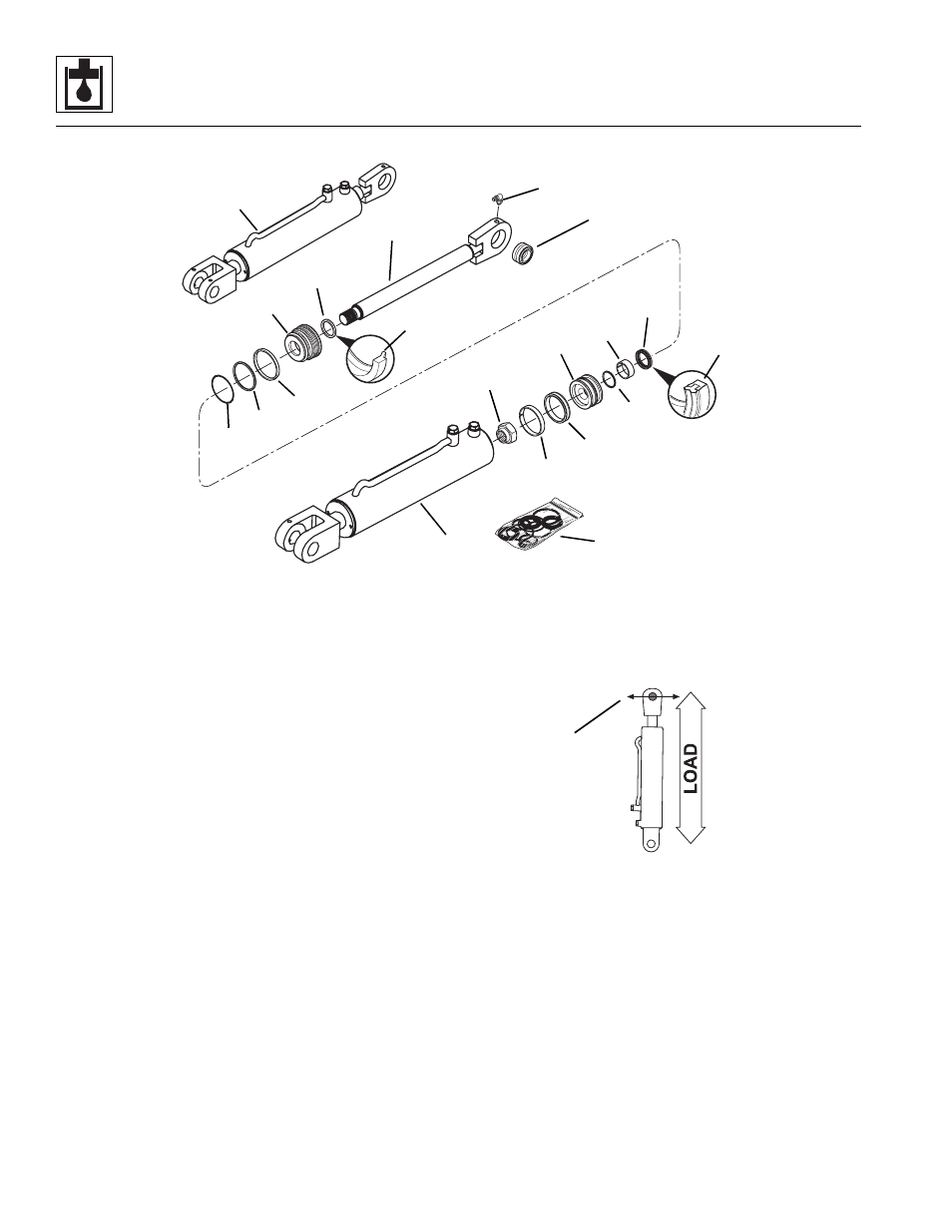
12. Install the bearing (20) into the rod end. When
installing the bearing, the fracture in the bearing race
must be positioned perpendicular (21) to the force of
the load.
f.
Slave Cylinder Installation
1. Align the slave cylinder with its mounting bosses on
the transfer carriage.
2. Align the mount pin bolt holes with the slave cylinder
mount holes. Refer to Section 3.3.3, “Outer Boom
Replacement,” and Section 11.3.2, “Transfer
Carriage Installation,” to install the slave cylinders.
3. Refer to Section 2.3, “Torques,” for fitting torque
values.
1
2
3
4
5
6
7
8
9
10
11
12
13
14
15
16
17
18
19
MU3570
20
MU4560
21