Section 9.14.10, “dual joystick, 10 dual joystick – Lull 944E-42 Service Manual User Manual
Page 737
9.227
Model 644E-42/944E-42
Rev. 6/04
Electrical System
9.14.10
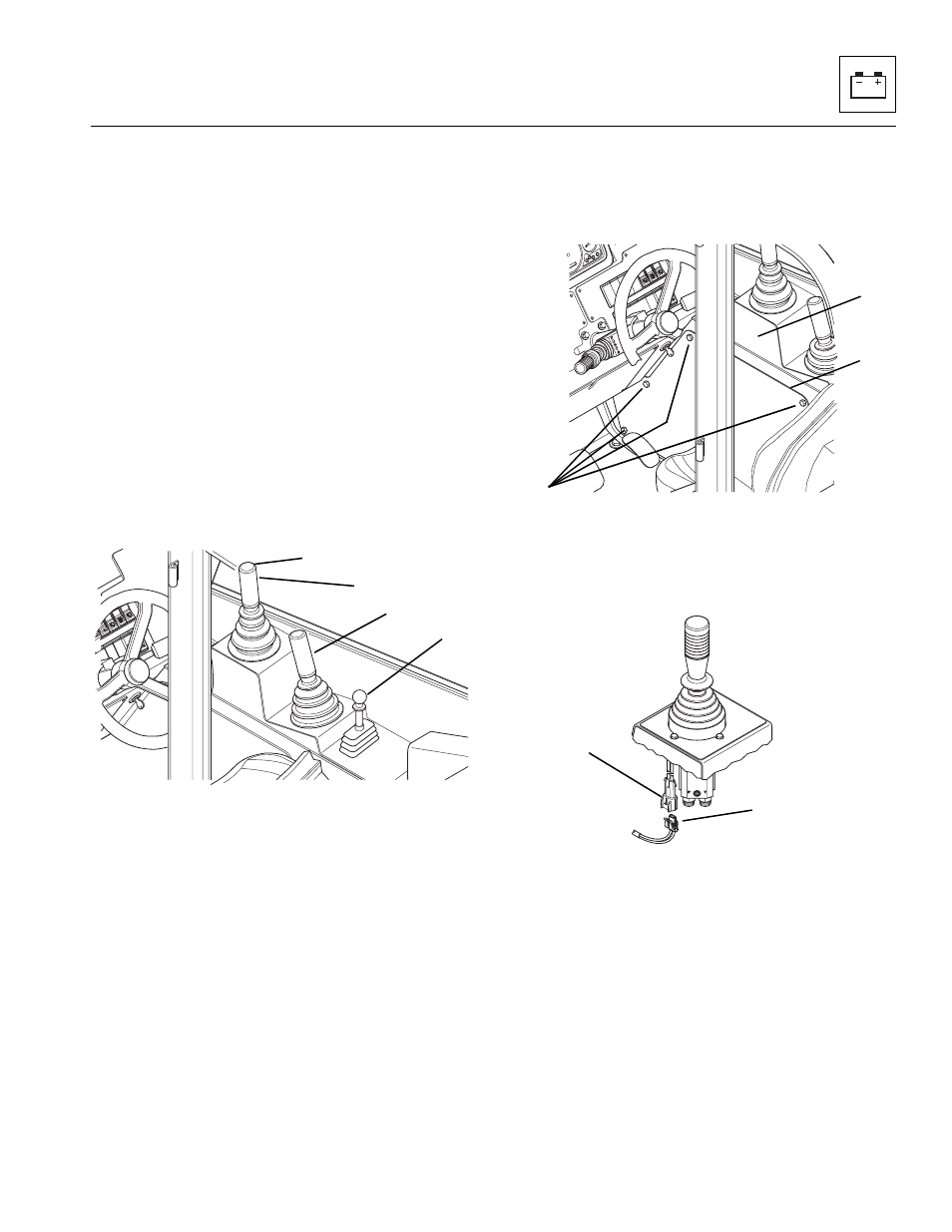
Dual Joystick
This vehicle is equipped with three separate hydraulic
joysticks.
• The front joystick (14) controls attachment tilt and
transfer carriage operation. The button (15) on the
front joystick controls the auxiliary hydraulic function.
(Refer to Section 9.8.29, “Dual Joystick - Auxiliary
Hydraulic Circuit & Troubleshooting.”)
This joystick is the only joystick that has an active
electrical button. This button activates the solenoids
on the selector valve which switches hydraulic flow
from the transfer carriage circuit to the auxiliary
hydraulic circuit.
• The middle joystick (16) controls boom lift/lower and
extend/retract functions.
• The rear joystick (17) controls the frame sway
function. This joystick is a single axis joystick with a
lift to shift lock ring detent and controls the frame
sway to the left and right
Two functions can be accomplished at the same time by
moving the joystick in between quadrants. For example,
moving the stick forward will lower the boom, and moving
the stick to the left will retract the boom; moving the
joystick forward and to the left will both lower and retract
the boom at the same time.
The speed of movement relates to the amount of joystick
movement away from the center position. The overall
speed of movement also depends directly on engine rpm.
Joystick mode operation can be checked according to the
joystick operation instructions found in the Owners/
Operators Manual for this vehicle. Operational checks will
indicate whether the system is working properly. If a
designated function does not occur as described, check
both the electrical and hydraulic circuit involved to
determine the cause.
a. Front Joystick Button Testing
1. Remove the six capscrews (18) (two not shown)
securing the access panel (19) to the side
console (20). Remove the access panel.
2. Disconnect the cab wire harness connector
plug (21) from the joystick connector plug (22).
3. Check the cab harness connector plug (21) with a
DMM for battery voltage. Place the negative (-) lead
on pin B and the positive (+) lead on the pin A, and
test for battery voltage.
If battery voltage is not present, the wiring harness is
suspect and should be replaced. If battery voltage is
present, the harness is functioning properly.
OU0410
14
15
16
17
MU4040
18
19
20
MU4090
21
22