Main control valve, S ( 13, Warning – Lull 944E-42 Service Manual User Manual
Page 429
8.177
Model 644E-42/944E-42
Rev. 6/04
Hydraulic System
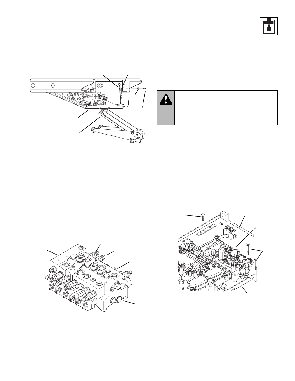
10. After the capscrews are removed, slowly lower the
sub plate down until the sub plate is supported on
the two tethers mounted to the cab support.
b. Sub Plate w/Valve Plate Removal
Refer to Section 4.5, “Cab Removal,” for sub plate
removal procedure and reassembly procedure.
8.12.2
Main Control Valve
The main control valve assembly (14) consists of various
working sections with their own valve assemblies, each
providing a specific hydraulic function. The section
assemblies are the inlet (15), transfer carriage spool
section (16), auxiliary hydraulic section (17) and the four
spool mono block section (18).
If service to the main control valve assembly is required,
swing the sub plate, w/valve plate assembly, down to
gain access to the valve and fittings. Refer to Section
8.12.1, “Valve Plate Assembly.”
a. Main Control Valve Removal from Valve Plate
Before disassembling the main control valve, remove it
from the valve plate assembly. Tag and remove all the
hoses from the fittings. Cap and plug all hoses ends and
fittings.
1. Wipe up any hydraulic fluid spillage in, on, near and
around the vehicle and the work area.
2. Secure the main control valve in place on the valve
plate to prevent sudden movement when the
hardware is removed.
3. With the sub plate w/valve plate assembly (19)
swung down from the cab, remove the two longer
capscrews (20) and the shorter capscrew (21)
securing the main control valve (22) to the valve
plate (23).
4. Remove the main control valve from the valve plate
by sliding the valve out between the valve plate and
the bottom of the cab.
MU3820
8
9
10
11
12
13
MU3860
14
15
16
17
18
WARNING:
Uncontrolled and sudden
movement of the main control valve can cause
personal injury. ALWAYS secure the valve, in
place, before loosening or removing any
mounting hardware.
MU3870
19
20
21
22
23