Lull 944E-42 Service Manual User Manual
Page 697
9.187
Model 644E-42/944E-42
Rev. 6/04
Electrical System
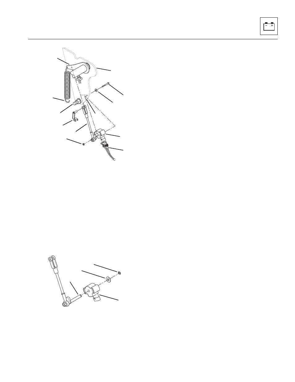
4. Disconnect the bottom of the return spring (16) from
the bolt (17) at the bottom of the mounting
bracket (18) inside the cab.
5. Remove the clevis locking pin (19) from the clevis on
the linkage assembly (20).
6. Remove the two slotted pan head screws (21), flat
washers (22) and nuts (23) securing the sensor and
linkage assembly to the mounting bracket.
7. Slide the sensor (15) and linkage assembly (20) out
of the slot (24) on the mounting plate (18).
8. Remove the snap ring (25) and flat washer (26)
securing the sensor (27) to the linkage
assembly (28).
c. Disassembly
DO NOT disassemble the sensor. The sensor is not
serviceable. Replace the sensor if found to be defective.
d. Cleaning and Drying
Without submerging the sensor, clean the sensor with an
approved solvent and dry with a clean, lint-free cloth.
e. Installation and Testing
1. Slide the sensor (27) onto the linkage assembly
shaft (28).
2. Lock in place on shaft using a flat washer (26) and
snap ring (25).
3. Slide the sensor (15) and linkage assembly (20) into
the slot (24) on the mounting plate (18).
4. Line up the hole in the clevis on the linkage
assembly (20) with the hole on the throttle pedal stop
plate (25).
5. Secure clevis with the clevis locking pin (19).
6. Secure the sensor to the cab mounting bracket (18)
with two slotted pan head screws (21), flat washers
(22) and nuts (23). Torque nuts to 2-4 lb-ft
(1.5-3 Nm).
7. Connect the ECM cab harness connector (14) to the
sensor (15).
8. If the vehicle has dual batteries, connect both
negative battery cables (8 and 9) to both batteries.
Connect the lower negative battery cable (8) to the
negative (-) terminal on the lower battery (10). Swing
the upper battery box (13) in and make sure that the
lip (12) on the upper battery box slides below the
knob (11). Secure in place with the knob.
9. Lower and lock engine cover. To release and lower
the engine cover (6) from the fully raised position, lift
up slightly on the cover and push the upper part of
the right gas shock (7) (orange tab) to the left. Line
up the upper part of the shock lock tube with the
lower part of the gas shock and pull the cover down
to the closed position.
10. Start the engine. Engine rpm should increase as
soon as the throttle pedal is depressed and continue
to increase until the throttle pedal is fully depressed.
If there is free play in the pedal stroke, refer to
Section 4.3.6, “Throttle Pedal Replacement,” for
adjustment procedure.
15
16
17
18
19
20
21
22
23
24
25
MU5740
14
MU5760
25
26
27
28