Lull 944E-42 Service Manual User Manual
Page 742
Electrical System
9.232
Model 644E-42/944E-42
Rev. 6/04
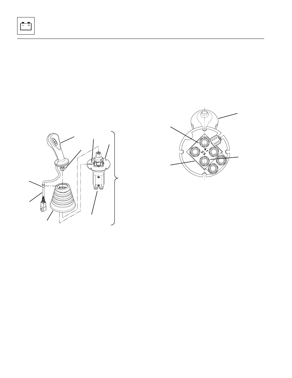
c. Late Production Single Joystick Handle
Replacement
1. Remove the front joystick valve assembly (1) from
the side console. Refer to Section 4.3.9, a. “Single
Joystick Assembly Removal.”
2. Secure the valve body (2) in a bench vise or by other
suitable means.
3. Roll the boot (3) up to expose the jam nut (4) at the
bottom of the handle assembly (5).
4. Lift the wire harness bushing (6) to clear the
retaining hole (7) in the ring on the joint
assembly (8). Slide the wire harness (9) out through
the slot.
5. Hold the nut on the top of the joint assembly in place
while loosening the jam nut (4) on the handle
assembly.
6. Remove the handle assembly (5) with the boot (3). If
not replacing the boot, remove the boot from the
handle assembly.
7. To assemble the new handle, slide the wire
harness (9) through the boot (3) and assemble the
boot to the handle assembly (5).
8. Roll the boot (3) up to expose the jam nut (4) at the
bottom of the handle assembly (5).
9. Thread the handle assembly (5) onto the joint
assembly (8).
10. Make sure that the center line on the handle (10) is
in line with ports 3 (11) and 4 (12) on the valve
body (13) before tightening the jam nut on the
handle assembly. Torque the handle assembly jam
nut (4) to 18 lb-ft (24 Nm).
11. Assemble the front joystick valve assembly (1) into
the side console. Refer to Section 4.3.8, b. “Front,
Rear and Frame Sway Joystick Assembly
Installation.”
d. Single Joystick Function Solenoid Valves
The single joystick commands are actuated, both
electrically and hydraulically, via a set of solenoid-
operated cartridges within the single joystick pilot select
valve (14). The single joystick pilot select valve is located
on the valve plate which is located under the cab floor.
As the solenoid coils (15 through 20) are energized/de-
energized, the cartridges open and close oil passages,
thereby directing hydraulic fluid flow to the appropriate
section of the main control valve.
MU6310
1
2
3
4
5
6
7
8
9
MU6250
10
11
12
13