15 transmission temperature switch, Electrical system – Lull 944E-42 Service Manual User Manual
Page 749
9.239
Model 644E-42/944E-42
Rev. 6/04
Electrical System
lift up slightly on the cover and push the upper part
of the right gas shock (2) (orange tab) to the left.
Line up the upper part of the shock lock tube with the
lower part of the gas shock and pull the cover down
to the closed position.
5. Clear the area around the vehicle of personnel and
any obstructions to vehicle travel.
6. Start the engine, allow it to reach operating
temperature, and observe the front dash panel for
sender indication. If the sender is not defective, the
problem could be elsewhere; possibly in a shorted
wire, improper-running engine, improper coolant,
obstructed or faulty radiator, water pump, loose fan
belt, defective display, etc. (Refer to Section 9.10.2,
“Engine Coolant Temperature Gauge
Troubleshooting.”)
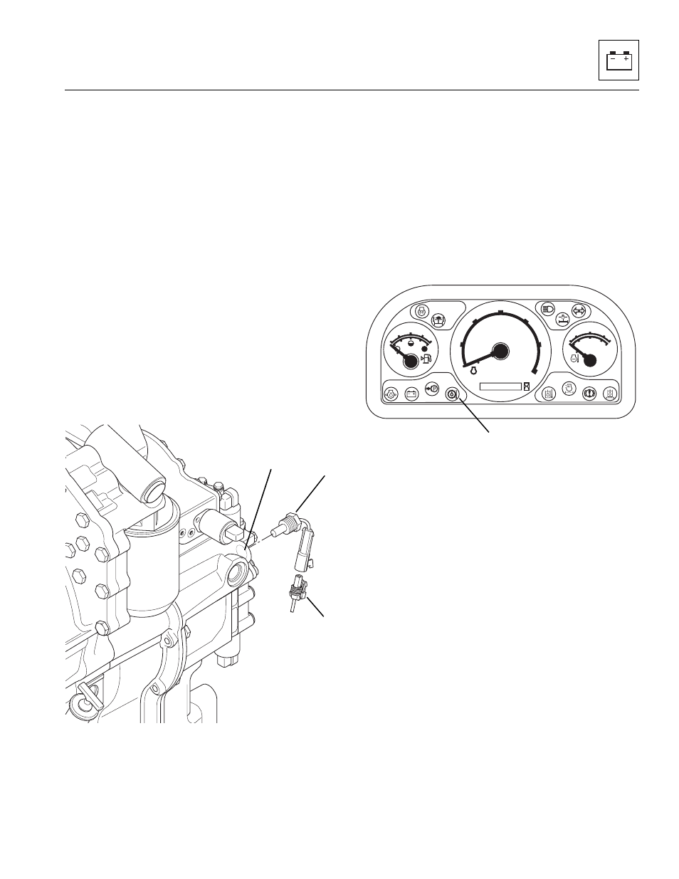
9.14.15
Transmission Temperature Switch
The transmission temperature switch (13) is threaded
into the transmission housing (14) and is connected via
the vehicle sensors wiring harness (15), bulkhead
connector and cab wiring harness to the front dash panel.
When the transmission fluid temperature rises above
250° F (121° C), the switch heats up, closing contacts
within the sending unit. The front dash panel
indicator (16) illuminates and an audible alarm will sound.
Stop and idle the vehicle with the transmission in (N)
Neutral, allowing time for cooling.
When the transmission temperature is below 250° F
(121° C), the contacts within the sending unit open and
the front dash panel indicator and alarm turn OFF. If the
light does not go out after two minutes, shut the vehicle
down. (Refer to Section 9.10.6, “Transmission
Temperature Warning Indicator Troubleshooting.”)
a. Transmission Temperature Switch Removal
1. Unlock and open the engine cover (1).
2. If the vehicle has dual batteries, disconnect both
negative battery cables (3 and 4) from both
batteries.
To access the lower battery (5), loosen the knob (6)
far enough so that the lip (7) on the upper battery box
clears the knob. Lift up the upper battery box (5) and
swing it out, so that the box clears the hydraulic tank
support bracket, to gain access to the lower negative
battery cable (3). Disconnect the lower negative
battery cable.
3. Unplug the switch (13) connector from the wiring
harness connector (15).
4. The switch (13) is threaded into the transmission
housing (14). Remove the switch.
MU4530
13
14
15
0000000
RPM X 100
5
10
15
30
20
25
F
1/2
E
104
176
80
248
120
°C
°F
D
r/min
MU0010
16