Lull 944E-42 Service Manual User Manual
Page 413
8.161
Model 644E-42/944E-42
Rev. 6/04
Hydraulic System
8.8.61
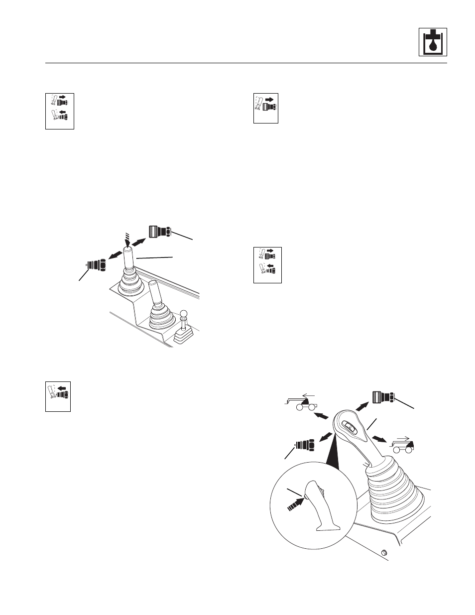
Auxiliary Hydraulic Circuit Description
(Dual Joystick)
The auxiliary hydraulic circuit (page 8.126,
page 8.128, page 8.134 or page 8.136)
functions can be achieved by pushing the
Button (5) down on the top of the Front Joystick
(6) and moving the joystick in the
corresponding direction. Moving the Joystick to the LEFT
controls auxiliary function in one direction by pressurizing
the Male Coupler (7). Moving the joystick to the RIGHT
controls auxiliary functions in the opposite direction by
pressurizing the Female Coupler (8). The Button must be
held down during operation of the auxiliary hydraulic or
the joystick mode will immediately return to the transfer
forward or back mode of operation.
a. Male Coupler Pressurized (page 8.126 or
With the Button held down on the top of the Front
Joystick, and the joystick moved to the LEFT,
pilot pressure from the Accumulator Charge/
Secondary Function Valve “PIL” Port to the
Joystick “P” Port, exiting Port “2” and flowing through the
Pilot Select Valve Port “P1,” exiting Port “B3” will shift the
auxiliary spool on the Main Control Valve, allowing
system pressure to flow from the auxiliary spool to the
MALE Auxiliary Hydraulic Coupler. From the Male
Coupler, fluid flows to the attachment, back to the
FEMALE Auxiliary Coupler, to the auxiliary spool, to the
Oil Cooler, to the Return Filter and then to the Hydraulic
Reservoir.
b. Female Coupler Pressurized (page 8.134 or
With the Button held down on the top of the Front
Joystick, and the joystick moved to the RIGHT,
pilot pressure from the Accumulator Charge/
Secondary Function Valve “PIL” Port to the
Joystick “P” Port, exiting Port “1” and flowing through the
Pilot Select Valve Port “P2,” exiting Port “A3” will shift the
auxiliary spool on the Main Control Valve, allowing
system pressure to flow from the auxiliary spool to the
FEMALE Auxiliary Hydraulic Coupler. From the Female
Coupler, fluid flows to the attachment, back to the MALE
Auxiliary Coupler, to the auxiliary spool on the Main
Control Valve, to the Oil Cooler, to the Return Filter and
then to the Hydraulic Reservoir.
8.8.62
Auxiliary Hydraulics Circuit
Description (Single Joystick)
The auxiliary hydraulics circuit (page 8.130,
page 8.132, page 8.138 or page 8.140)
functions can be achieved by pushing the
Trigger Button (9) in on the Single Joystick (10)
and moving the joystick in the corresponding
direction. Moving the joystick to the LEFT controls
auxiliary function in one direction by pressurizing the
MALE coupler (11). Moving the joystick to the RIGHT
controls auxiliary functions in the opposite direction by
pressurizing the FEMALE coupler (12). The Trigger
Button must be held down during operation of the
auxiliary hydraulics or the joystick mode will immediately
return to the extend the boom forward or back mode of
joystick operation.
MU0060
5
6
7
8
OU0450
MU0070
MU0080
MU0060
9
10
11
12
MU6290