Warning – Lull 944E-42 Service Manual User Manual
Page 448
Hydraulic System
8.196
Model 644E-42/944E-42
Rev. 6/04
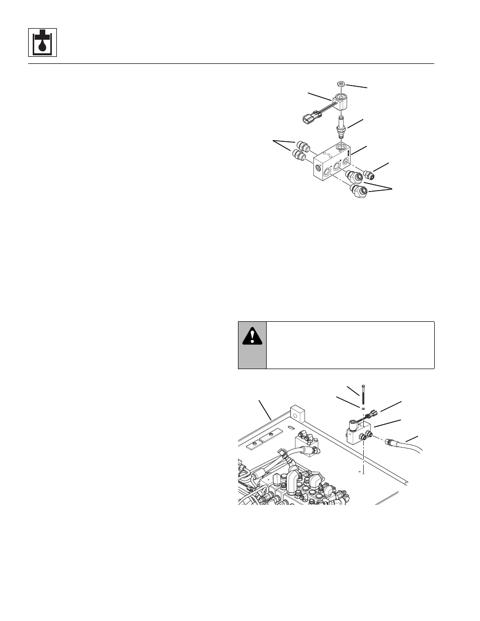
b. Auxiliary Hydraulic Pressure Release Valve
Disassembly, Inspection and Reassembly
Note: Use new oiled o-rings as required. ALWAYS
replace seals, o-rings, gaskets, etc., with new parts to
help ensure proper sealing and operation. Lubricate
seals and o-rings with clean hydraulic oil.
Note: Torque all the fittings as specified in Section 2.3,
“Torques.”
1. Remove the elbow fittings (1) from the “A” and “B”
ports on the valve block (2).
2. Remove the straight fittings (3) from the “A” and “B”
ports on the valve block and the “Drain” port (4).
3. Remove the solenoid cartridge (5) from the valve
block.
4. Clean all components with a suitable cleaner before
inspection.
5. Inspect internal passageways of the auxiliary
hydraulic pressure release valve and its component
parts for wear, damage, etc. If inner surfaces of the
auxiliary hydraulic pressure release valve DO NOT
display an ultra-smooth, polished finish, or
components are damaged in any way, replace the
auxiliary hydraulic pressure release valve or
appropriate part. Often, dirty hydraulic fluid causes
failure of internal seals and damage to the polished
surfaces within the auxiliary hydraulic pressure
release valve.
6. Secure the auxiliary hydraulic pressure release valve
block (2) in a bench vise or by other suitable means.
7. Install the elbow fittings (1) into port “A” and “B” on
the valve block. Torque to 50-60 lb-ft (67-81 Nm).
8. Install the straight fittings (3) into port “A” and “B” on
the valve block. Torque to 50-60 lb-ft (67-81 Nm).
9. Install a straight fitting (4) into port “Drain” on the
valve block. Torque to 24-26 lb-ft (32-35 Nm).
10. Install the solenoid cartridge (5) into the valve block.
Torque the solenoid (6) to 20 lb-ft (27 Nm). Torque
the solenoid nuts (7) to 5 lb-ft (7 Nm).
c. Auxiliary Hydraulic Pressure Release Valve
Installation
1. Position the auxiliary hydraulic pressure release
valve (8) back onto the valve plate (9).
2. Replace the two capscrews (10) and washers (11)
through the auxiliary hydraulic pressure release
valve (8) and secure to the valve plate (9). Torque
the two capscrews to 5-9 lb-ft (7-12,5 Nm).
3. Reattach and secure all hoses (12) and fittings.
4. Reconnect the wire harness connector (13).
WARNING:
Avoid prolonged engine
operation in closed areas with inadequate
ventilation. Failure to properly ventilate exhaust
fumes can result in death or serious injury.
MU5890
1
2
3
4
5
6
7
B
A
MU5840
12
8
13
10
9
11