Section 8.12.5, “joystick valve (single joystick), Joystick valve (single joystick) – Lull 944E-42 Service Manual User Manual
Page 440
Hydraulic System
8.188
Model 644E-42/944E-42
Rev. 6/04
8.12.5
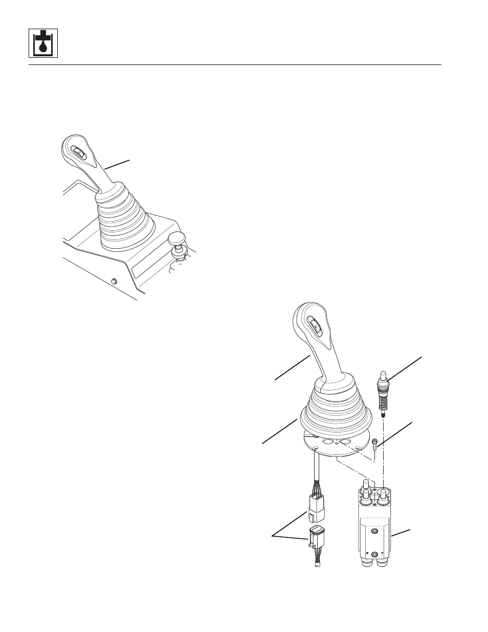
Joystick Valve (Single Joystick)
The joystick valve is part of the joystick assembly (1).
Joystick commands are actuated both electrically and
hydraulically via a set of solenoid-operated control valves
mounted in an array at the pilot select manifold.
Verify the correct operation of the joystick switches and
circuit solenoids before considering replacement of the
joystick valve. Refer to Section 9.14.11, “Optional Single
Joystick.” The valve itself is not serviceable and must be
replaced in its entirety if replacement of electrical parts
does not resolve the problem. Refer to Section 4.3.9,
“Single Joystick Assembly Replacement (Optional).”
After replacing the joystick valve assembly, check all
joystick functions.
a. Single Joystick Capsule Replacement
1. Remove the entire single joystick assembly from the
cab. Refer to Section 4.3.9, a. “Single Joystick
Assembly Removal.”
2. Secure single joystick body in a vice or suitable
device.
3. Disconnect the joystick harness connection (2).
4. Lift up the boot (3) and remove the capscrews (4)
that secure the joint and handle assembly (5) to the
valve body (6). Lift the joint and handle assembly
from the top of the valve body.
5. Remove the capsules (7) from the valve body (6).
6. Clean all components with a suitable cleaner before
inspection.
7. Inspect internal passageways of the pilot select
valve and its component parts for wear, damage, etc.
If inner surfaces of the pilot select valve DO NOT
display an ultra-smooth, polished finish, or
components are damaged in any way, replace the
pilot select valve or appropriate part. Often, dirty
hydraulic fluid causes failure of internal seals and
damage to the polished surfaces within the pilot
select valve.
8. Assemble the new capsule assembly (7), with the o-
ring lightly oiled, into the valve body (6).
9. Reassemble the joint and handle assembly (5) to the
valve body (6). Torque the capscrews (4) to 6-8 lb-ft
(8-10,8 Nm).
10. Reassemble the boot (3) to the joint and handle
assembly (5).
11. Reconnect the joystick harness connection (2).
12. Replace joystick body into cab. Refer to Section
4.3.9, b. “Single Joystick Assembly Installation.”
After replacing the joystick valve assembly, check all
joystick functions.
MU6300
1
MU6320
2
3
4
5
6
7