Valves and manifolds, Section 8.12, “valves and manifolds.”), 12 valves and manifolds – Lull 944E-42 Service Manual User Manual
Page 428: Valve plate assembly, Warning
Hydraulic System
8.176
Model 644E-42/944E-42
Rev. 6/04
8.12
VALVES AND MANIFOLDS
Valves are devices that open or close passageways.
Manifolds contain circuit passageways involved in the
distribution of hydraulic fluid flowing under pressure.
There are various valves and manifolds in use on this
vehicle. As valves open and close, hydraulic fluid is
directed to flow through various passageways to the
prescribed circuit, causing vehicle functions to occur.
8.12.1
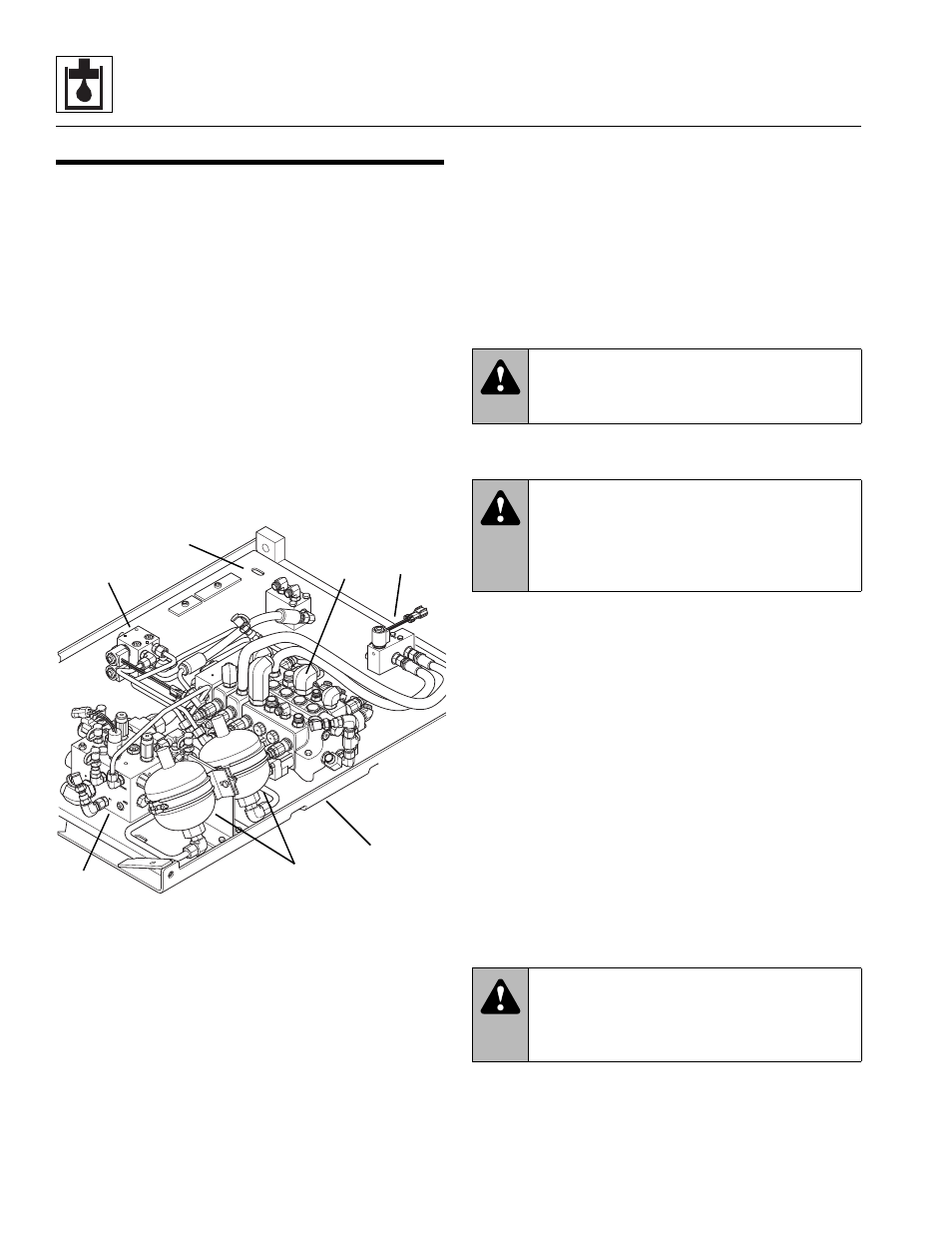
Valve Plate Assembly
The main control valve (1), accumulators (2),
accumulator charge/secondary function valve (3),
auxiliary hydraulic pressure release valve (4) and the pilot
select valve (5) are mounted on a valve plate (6) which is
bolted to the sub plate (7) located under the cab. The sub
plate can be swung down for servicing of components or
removed from the cab mount for valve removal.
Follow the procedure in this section to swing down the
sub plate (6) and valve plate assembly (5) from the
vehicle in order to service the main control valve (1),
accumulators (2), accumulator charge/secondary
function valve (3), auxiliary hydraulic pressure release
valve (4) and the pilot select valve (5).
a. Sub Plate w/Valve Plate Lowering
1. Park the vehicle on a firm, level surface, fully retract
all hydraulic cylinders, raise the boom, place the
travel select lever in the [N] NEUTRAL DETENT
position, level the vehicle side to side, engage the
park brake switch and shut the engine OFF.
2. Place an Accident Prevention Tag on both the
ignition switch and the steering wheel, stating that
the vehicle should not be operated. Refer to Section
1.5, “Accident Prevention Tag Usage.”
3. Unlatch and open the engine cover. Allow the
hydraulic fluid to cool.
4. Remove the access plate from the cab floor to gain
access to the hose and tube fittings on the valve
plate which is located under the cab.
5. Thoroughly clean the main control valve and
surrounding area, including all hoses and fittings,
before proceeding.
6. Label or otherwise mark the hydraulic hoses and
tubes at the main control valve, accumulator charge/
secondary function valve or selector valve. Place a
suitable container to catch hydraulic fluid drainage
beneath the cab.
7. Remove the step assembly from the side of the cab.
Refer to Section 4.5, “Cab Removal,” for step
removal procedure.
8. Check to be sure the two tethers (8) are positioned
in the two mounting tabs (9) on the front and rear
sides of the cab mount. If not, place the loop of the
tether in the mount before proceeding.
9. Place a floor jack (10) under the outer edge of the
sub plate (11) to hold the sub plate in position while
removing the two capscrews (12) and washers (13)
securing the sub plate to the cab support.
B
A
MU5950
1
2
3
4
5
7
6
WARNING:
Hot hydraulic fluid can
cause severe burns. Wait for hydraulic fluid to
cool before servicing any hydraulic component.
WARNING:
Escaping hydraulic fluid
under pressure can penetrate the skin, causing
death or serious injury. Relieve hydraulic
pressure before servicing any hydraulic
component.
WARNING:
Uncontrolled lowering of the
sub plate assembly can cause personal injury.
ALWAYS support the sub plate before
loosening or removing any mounting hardware.