Valve plate installation, Section 4.7.2, “valve plate installation – Lull 944E-42 Service Manual User Manual
Page 139
4.35
Model 644E-42/944E-42
Rev. 6/04
Cab and Covers
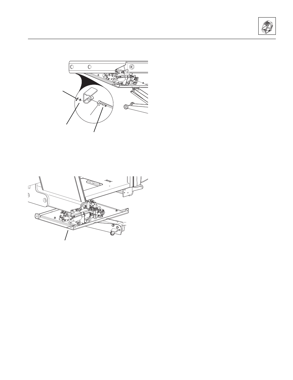
9. Remove the two cotter pins (15), washers (16) and
valve plate hinge pins (17).
10. Disconnect, label, cap and plug all hose connections
and fittings.
11. Disconnect and label all electrical connections.
12. Remove the valve plate (18) from the vehicle.
13. Service individual valve plate components as
required. (Refer to Section 8.12, “Valves and
Manifolds.”)
4.7.2
Valve Plate Installation
1. Use a suitable lifting device to lift the valve plate (18)
into position under the cab.
2. Reconnect all of the electrical and hydraulic
connections to their previously labeled positions. (To
properly reconnect all hydraulic connections, refer to
Section 2.3, “Torques.”)
3. Replace the hinge plate pins (17), washers (16) and
cotter pins (15) to secure valve plate (10) to the cab
mount frame (13).
4. Reconnect the two tethers (14) to the cab mount
frame (13).
5. Lift the valve plate and secure with two
capscrews (11) and washers (12). Torque the
capscrews to, 43-78 lb-ft (59-106 Nm).
6. Attach a suitable lifting device to the cab step (7) and
lift into position under the cab.
7. Replace four capscrews (8) and washers (9)
securing the cab step (7). Torque the capscrews to,
43-78 lb-ft (59-106 Nm).
8. If the vehicle has dual batteries, connect both
negative battery cables (1 and 2) to both batteries.
Connect the lower negative battery cable (1) to the
negative (-) terminal on the lower battery (3). Swing
the upper battery box (6) in and make sure that the
lip (5) on the upper battery box slides below the
knob (4). Secure in place with the knob.
MU4930
15
16
17
MU3980
18