Lull 944E-42 Service Manual User Manual
Page 689
9.179
Model 644E-42/944E-42
Rev. 6/04
Electrical System
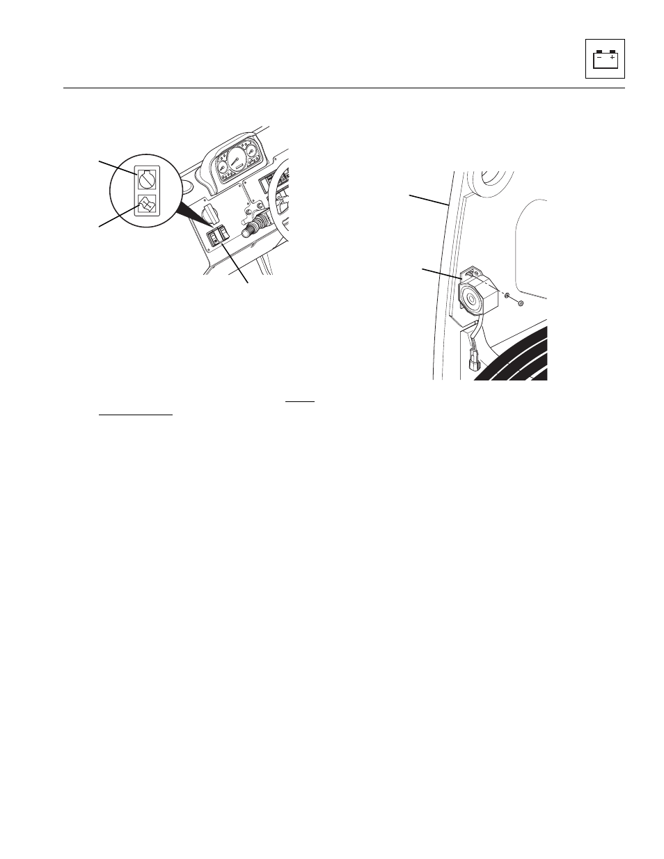
c. Engine Function Indicator Lights
The engine function indicator lights (8) are located on the
left side of the front dash between the park brake switch
and the transmission disconnect switch. The light
indicates any faults that arise in the engine during
operation. The light contains a RED light (9) and a
AMBER light (10).
If the RED light (9) comes ON during operation STOP the
engine IMMEDIATELY and diagnose the fault by
activating the ECM diagnostic system. Activate the
system with the accelerator pedal. Activate the system
and read the code as indicated by the light. Refer to the
Section 9.8.2, b. “Flash-Out of Fault Codes,” or the
appropriate owners/operators manual for instructions to
activate the system. Refer to your local Cummins dealer
for an explanation of the code, refer to the Cummins
Engine Owners Manual or call the Cummins Customer
Assistance Center at 1-800-343-7357.
If the AMBER light (10) comes ON during operation the
engine diagnostic system has detected a fault within the
engine. Stop the engine and diagnose the fault by
activating the ECM diagnostic system. Activate the
system and read the code as indicated by the light. Refer
to your local Cummins dealer for an explanation of the
code, refer to the Cummins Engine Owners Manual or
call the Cummins Customer Assistance Center at
1-800-343-7357.
d. Back-Up Alarm
The back-up alarm (11) is located at the rear of the
vehicle, mounted on the left side plate (12) of the transfer
carriage.
When the transmission shift control switch (travel select
lever) is shifted to the reverse position, the back-up alarm
will automatically sound. Place the travel select lever in
reverse to test the back-up alarm. The back-up alarm
must not sound when the travel select lever is in
NEUTRAL DETENT (N) or FORWARD (F). Also, with the
ignition switch in the RUN position, the back-up alarm will
sound when the travel select lever is shifted into the
REVERSE (R) position.
With the vehicle traveling in reverse, the back-up alarm is
energized via current from the transmission shift control
switch, part of the travel select lever mounted within the
steering column. See the appropriate wiring schematic
and diagram in this section to help understand the back-
up alarm circuit. Refer to Section 4.3.2, “Steering Wheel,
Transmission Travel and Gear Select Lever and Turn
Signal Select Lever,” for information on removing and
replacing the transmission shift control switch.
MU5690
8
9
10
MU3430
11
12