Lull 944E-42 Service Manual User Manual
Page 422
Hydraulic System
8.170
Model 644E-42/944E-42
Rev. 6/04
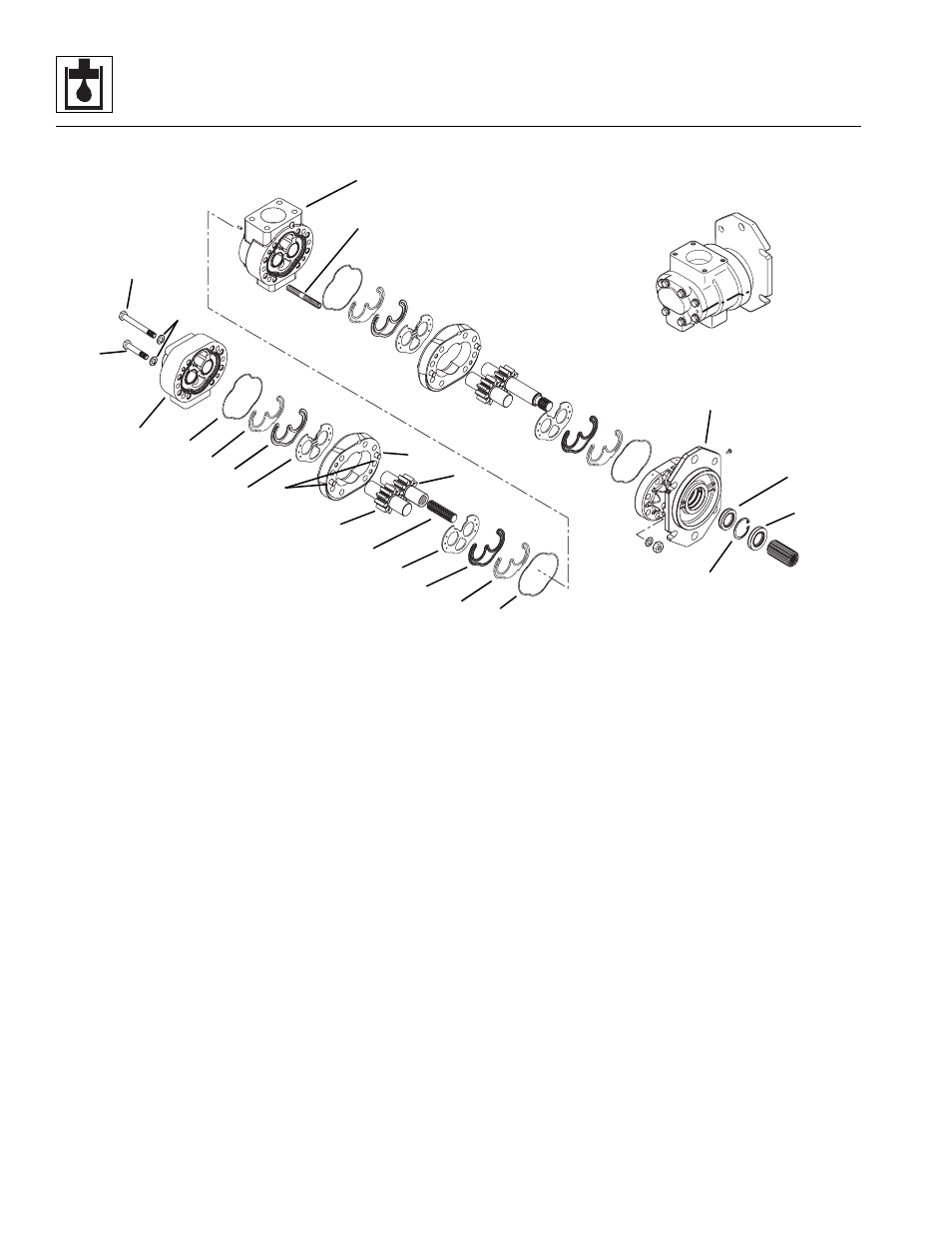
g. Pump Assembly
IMPORTANT: It is important that the relationship of the
front cover, front center section, ported section and
center section is correct. Notches cast into the outside
surfaces of these three parts must be aligned for proper
reassembly of this pump. Also, use the alignment marks
put on the side of the housing sections for reassembly.
Failure to properly assemble this pump will result in low
flow, low pressure and possible damage to the pump.
1. Rinse all parts in an approved solvent. Blow dry and
wipe the parts with a clean, lintless cloth before
beginning assembly.
Note: Upon reassembly of the pump, all parts should be
lightly oiled with clean hydraulic oil. Use small amounts
of graphite grease to hold seals and seal retainers in
place during assembly.
2. Apply a light coating of graphite grease to the new
square cross section o-ring (1) and carefully install
into the groove in the front side of the ported
section (2). Be careful that the o-ring does not twist
in the groove. The o-ring must be flat in the groove
for proper sealing of the pump when assembled.
3. Coat both the new seal gland (3) and new plastic
seal retainer (4) with graphite grease. Carefully
install the seal gland in the groove in the seal
retainer, make sure the seal gland is seated
completely in the seal retainer.
4. Coat the seal cavity area in the ported section with
graphite grease to hold the new seals in place during
assembly.
5. Install the assembled seal gland and seal retainer in
the cavity in the ported section (2). Be sure the
plastic seal retainer (4) is facing away from the
ported section. Very carefully press this assembly in
place until it is firmly seated in the machined recess.
This assembly must be seated completely in the
recess to allow proper installation of the bronze wear
plate (5).
6. Lubricate the steel side of the bronze wear plate (5)
with graphite grease and install over the seal retainer
and seal gland assembly. When properly installed
the bronze face will be next to the gears and flush
with the surface of the ported section.
7. Insert the splined adapter shaft (6) into the splined
end of the drive gear (7).
MM3561
1
2
3
4
5
6
7
8
9
10
11
12
13
14
15
16
17
18
19
20
22
21
23