T ( 11 ), On ( 5 ), D ( 4 ) – Lull 944E-42 Service Manual User Manual
Page 495: P ( 19 ), Ng ( 6 ), D ( 4, On ( 5
8.243
Model 644E-42/944E-42
Rev. 6/04
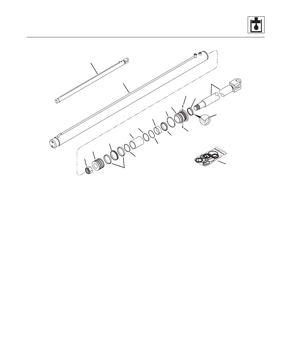
Hydraulic System
11. Secure the rod eyelet in a soft-jawed vise or other
suitable holding device. Place a padded support
below the threaded end of the rod to help prevent
damaging the rod.
12. Apply Loctite Primer “T” and Threadlocker #271
(red) to a new locknut (11) in accordance with Loctite
instructions. Install the nut onto the threaded end of
the rod. Torque the nut to 500-550 lb-ft
(678-746 Nm).
IMPORTANT: Avoid using excess force when clamping
the cylinder in a vise. Apply only enough force to hold the
cylinder securely. Excessive force can damage the
cylinder tube (2).
13. Fasten the tube (2) in a soft-jawed vise or other
suitable holding device.
14. Lubricate the o-rings and the inside of the tube,
piston and head gland with clean, filtered hydraulic
oil. This will aid in installation.
IMPORTANT: Use a suitable installation tool or
compression sleeve to help prevent twisting or damaging
the seals and o-rings when installing the piston (5) and
head gland (4) into the cylinder. When sliding the rod
and piston assembly in the tube, DO NOT damage the
piston by scraping it against the threads in the tube.
Keep the rod in line with the tube to prevent binding.
15. Keep the rod (3) straight and carefully insert the rod
into the tube (2). Avoid scratching, nicking or
damaging the tube while installing the rod.
16. Begin threading the head gland (4) into the tube (2).
Place the locking inserts (8) into the holes in the
head gland threads just before the holes are
threaded into the tube. Use a suitable pin spanner
wrench to thread the head gland (4) completely into
the tube (2). Torque the head gland to 250-300 lb-ft
(339-407 Nm).
17. Test the cylinder at low operating pressure
(100 psi or 6,9 bar) to verify that the piston and rod
move freely in both directions.
18. Increase the operating pressure to the maximum for
the cylinder (3500 psi or 241 bar) and check for
external leakage and for free movement in both
directions.
19. Retract the piston fully.
MU3800
1
2
3
4
5
6
7
8
9
10
11
12
13
14
15
16
17
18
19