8 kalatel dome – Videotec DCT User Manual
Page 99
6.8 KALATEL Dome
6.8.1
Materials and reference documents
Dome Kalatel CyberDome Pan/Tilt 18
× Day/Nite PAL
Kalatel Reference Manual ASCII Protocol 1038010A / January 2003
CyberDome Series Installation Manual A06-8SG0/B/April2006
CyberDome Installation Addendum.
6.8.2
Connecting the dome hardware
DCT
RJjack1
DOME
Connection diagram
RS485A
white
RS422 A
RS485B
yellow
RS422 B
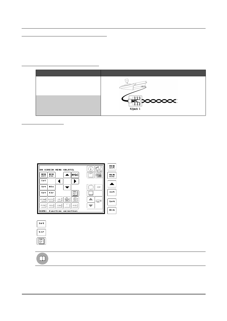
6.8.3
Configuration
The dome is configured by On Screen Menù.
For all dome configuration operations the “Setup Telemetry” FUNCTION must be enabled (see § 4.2.4.5 -
Functions, page 35).
Connect the dome directly to the keyboard and a monitor to the video OUT on the dome according to the
general procedure (see § 6.19 - Operating procedure for setting a dome/receiver, page 137).
Go to the OSM setup menu for the dome (see § 6.1.5 - Layout of the configuration menus, page 76) where it is
possible to make the various parameter settings.
ENTER PROGRAMMING
To enter the dome OSM.
EXIT PROGRAMMING
To exit the dome OSM.
DIRECTION ARROWS
Up, Down, Left, Right arrows to shift around menus.
1
st
To be used as indicated in the dome handbook.
SEQUENCE
To be used as indicated in the dome handbook.
ALARM
To be used as indicated in the dome handbook.
SET
To be used as indicated in the dome handbook.
CLEAR
To be used as indicated in the dome handbook.
NUMERIC KEYPAD
For inserting numeric values.
See the dome handbook.
Page 97 of 176
MNVADCT03_0716