11 pelco dome – Videotec DCT User Manual
Page 115
6.11 PELCO Dome
6.11.1
Materials and reference documents
Pelco Spectra II 3.31 dome.
Pelco Protocol Manual, “D” Protocol, March 2, 1999.
6.11.2
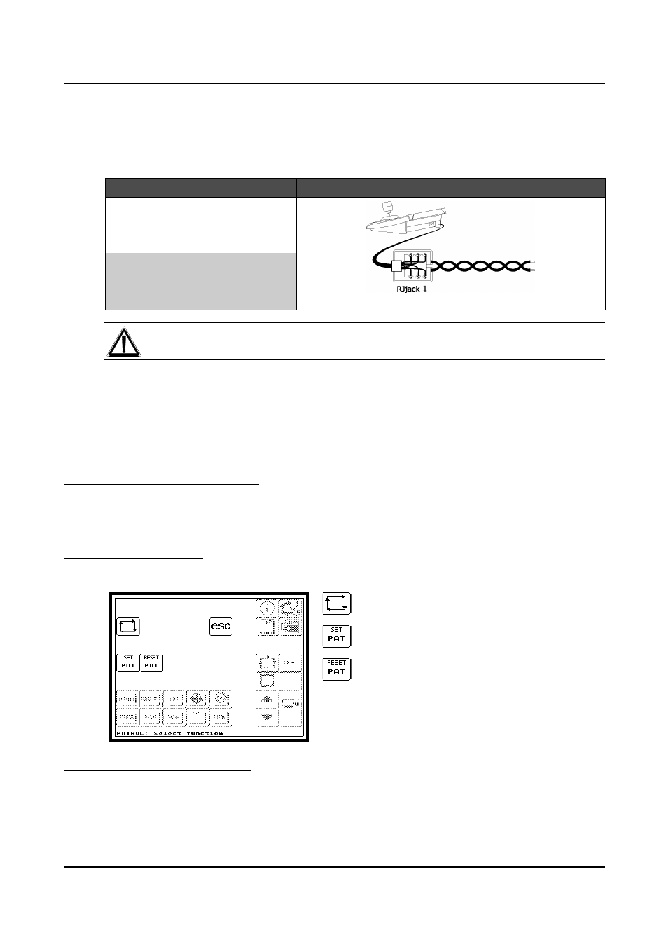
Connecting the hardware to the dome
DCT
RJjack1
DOME
Connection diagram
RS485A
white
Rx+
RS485B
yellow
Rx-
WARNING
The dome should be configured to use the “D” Type Protocol.
6.11.3
Configuratio
n
The parameters can be configured by inserting a special code (see § 6.11.7 - Special codes, page 114).
For all dome configuration operations it is necessary to enable the "Setup telemetry" FUNCTION (see §
4.2.4.5 - Functions, page 35).
Follow the general procedure to connect the dome directly to the keyboard and a monitor to the dome video
OUT (see § 6.19 - Operating procedure for setting a dome/receiver, page 137).
6.11.4
Autoflip, Aux, Focus, Iris
All these functions can be loaded by pressing the specific keys in the control menu area of the Main menu (see
§ 4.4 – Control menu area, page 45). Refer to § 9.1 – Functions assigned to the most common graphics keys,
page 164 and § 9.2.1 – Dome, page 165 to check which functions are available for the dome.
6.11.5
Patrol (Pattern)
In the Main menu press the PATROL key to enter the menu for carrying out the movement controls.
START PATTERN
To start the Pattern.
SET PATTERN
To enable Pattern setup.
STOP PATTERN
To end Pattern setup.
6.11.6
Preset, Scan and Home
The PRESET, SCAN and HOME functions are described in sections (§ 4.4.1.1 - PRESET, page 46 and §
4.4.2 - SCAN MENU, page 48).
Refer to § 9.2.1 – Dome, page 165 to check the specific limits of the dome.
Page 113 of 176
MNVADCT03_0716