3 connectors, 4 adjusting the contrast – Videotec DCT User Manual
Page 12
2.2 Appliances that can be connected to the DCT keyboard
2.2.1
Video Matrixes/DVR's/Multiplexers
See § 4.2.3.1.1 - Type – Protocol – Baud rate, page 23.
2.2.2
Domes/Camera/Receivers
See § 4.2.3.2.2 - Protocol – Baud rate, page 26.
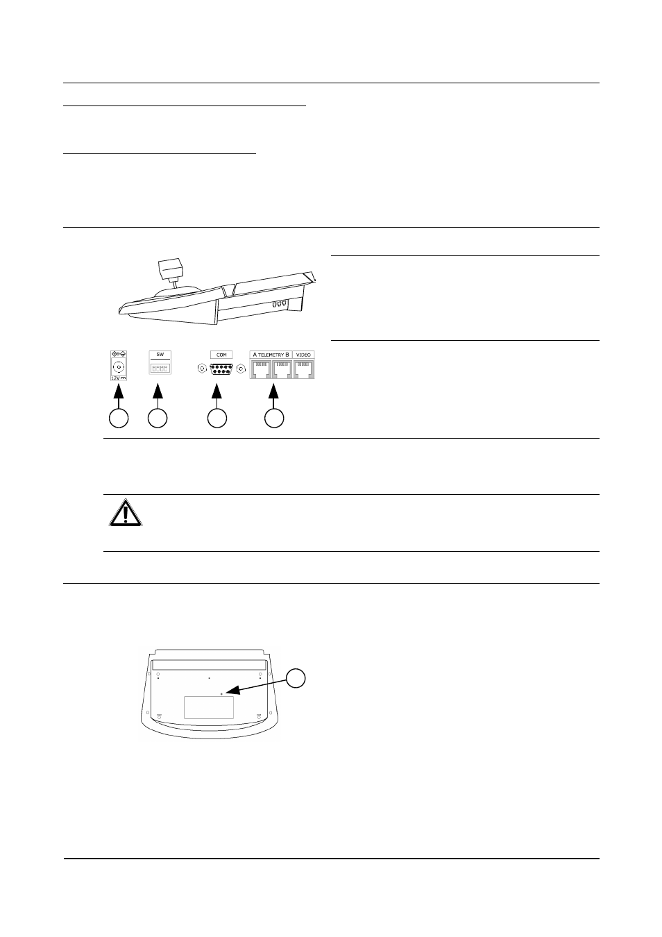
2.3 Connectors
The keyboard has three RJ11 connectors on the back of
the machine, a power supply connector, a configuration
DIP switch and a DB9 socket for connection with the
Personal Computer.
1. Power supply connector
2. DIP switch
3. DB9 Connector
4. Three RJ11 connectors
The VIDEO line is used to control the video system connected to the keyboard. TELEMETRY lines A and B
are used to control the first and second telemetry channels respectively. The DIP switch is used to insert or
remove the 120 Ohm termination load for each RS485 line (see § 3.2 - RS485 and types of systems, page 14)
and to enable communication with the PC.
5.
To prevent the risk of electrical shock, disconnect the cables from the RJ11 connectors before
connecting the COM line.
6. Do not connect the external communication lines (connected to RJ11 connectors) to the keyboard
at the same time as the serial line used by the PC.
2.4 Adjusting the contrast
Underneath the keyboard there is a hole to reach the trimmer for the keyboard contrast adjusting.
Using a flat-headed screwdriver with a fine tip, it is possible to adjust the trimmer until the best visibility is
obtained.
1. Hole for making adjustment
Page 10 of 176
MNVADCT03_0716
1
1
3
4
2