Videotec DCT User Manual
Page 175
10.2.2.5
Group 3 – Function control + video switching control
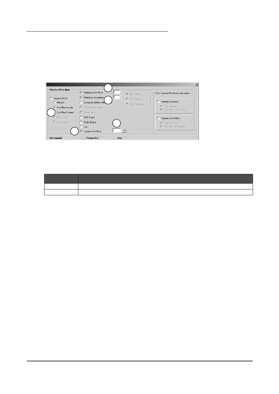
We associate the various parameter values with each of the two buttons, following the sequence shown in the
illustration:
1. Select “Local DVR/MUX”;
2. Select “Select DVR/MUX” and insert the address of the device (1 in this case);
3. Select “Select camera” and insert the camera number (1 in this case).
4. Select “DVR/MUX functions”;
5. Insert the number of the function (between 0 and 127) to be associated with the key.
Selecting a function-type
control
and
a
video
switching control
When the first key is pressed the function control with the value 0 will be sent, followed by the command to
load camera No. 2 of the device with address No. 1.
When the second key is pressed, on the other hand, the function control with the value 1 will be sent, followed
by the command to load camera No. 2 of the device with address No. 1.
These are the controls that will be transmitted in sequence from the keyboard when the keys are pressed:
BUTTON
CONTROLS
1
[VA0KB1FreM0,1I]
[VA0KB1VidS1,1V]
2
[VA0KB1FreM1,1J]
[VA0KB1VidS1,2W]
Page 173 of 176
MNVADCT03_0716
1
2
3
4
5