Videotec DCT User Manual
Page 59
5.3.2.2
SM328A
model
The matrix can be used either individually (a single matrix present in the system, controlled by one or more
keyboards) or in composite parallel or master/slave connection, where more than one matrix is controlled by
more than one keyboard.
See the matrix handbook for further information about this.
For connection, operational test and setup, see § 5.3.2.1.1 - Connection and operational test, page 56 and §
5.3.4.1 - Macro OSM, page 58.
5.3.2.3
SW328
model
For connection and operational test see § 5.3.2.1.1 - Connection and operational test, page 56.
The matrix does not require specific configuration.
WARNING
The SW328 matrix can be configured to disable control by a keyboard in set periods during the
day or in particular situations. In this case switching will be impossible. See the corresponding
handbook.
5.3.2.4
SW164OSM
model
5.3.2.4.1
Connection and operational test
WARNING
Inside the matrix both jumpers JP1and JP2 must be set for RS232 type communication. See the
corresponding handbook.
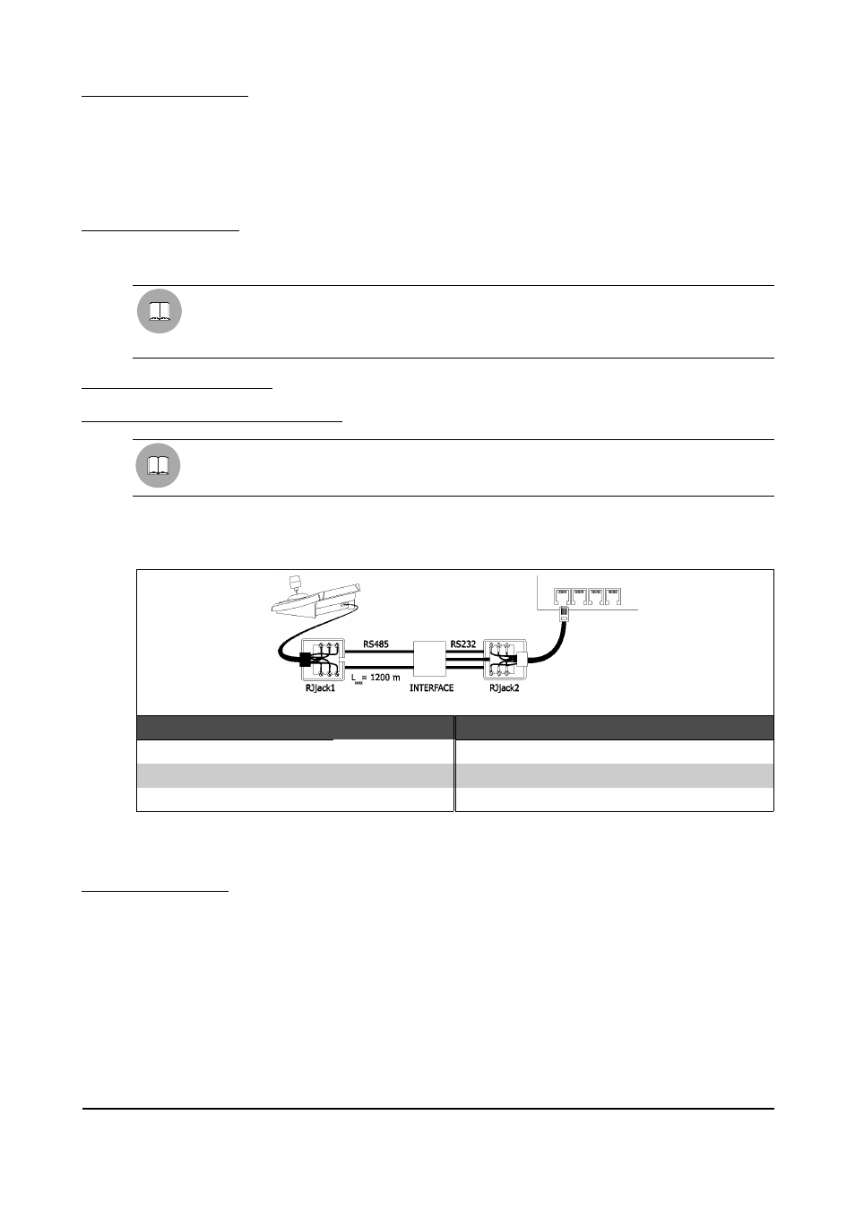
The connection between keyboard and matrix is made using an RS485 channel that must be converted into
RS232 using a special interface to be placed between the Video OUT connector on the keyboard and one of
the matrix connectors.
The connection diagram is as follows:
DCT
RJjack1
Interface IN
Interface OUT
RJjack2
SW164OSM
RS485A
white
A
RX
yellow
TX
--
--
--
TX
white
RX
RS485B
yellow
B
GND
red
GND
On completing the connection it should be immediately possible to switch the input videos using the
video/telemetry controls.
5.3.2.4.2
Matrix setup
The matrix can be set up via the corresponding menu (see § 5.3.4.2 - VIDEOTEC 164OSM OSM, page 59).
Page 57 of 176
MNVADCT03_0716