16 vcl dome – Videotec DCT User Manual
Page 128
6.16 VCL Dome
6.16.1
Materials and reference documents
VCL 8” Interner Dome .
Details of VCLTP Protocol, file ref. CIMICRO8 26.05.99.
6.16.2
Connecting the hardware to the dome
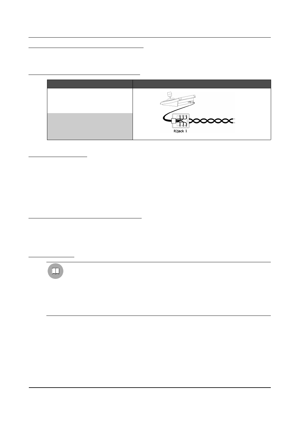
DCT
RJjack1
DOME
Connection diagram
RS485A
white
Data+
RS485B
yellow
Data-
6.16.3
Configuration
For the models that allow it, the dome is configured by On Screen Menu.
For all dome configuration operations it is necessary to enable the "Setup telemetry" FUNCTION (see §
4.2.4.5 - Functions, page 35).
Follow the general procedure to connect the dome directly to the keyboard and a monitor to the dome video
OUT (see § 6.19 - Operating procedure for setting a dome/receiver, page 137).
Go to the OSM configuration page (see § 6.1.5 - Layout of the configuration menus, page 76). When the setup
key is pressed the “Camera setup” command will be sent to the dome (only for the domes where this is
allowed).
6.16.4
Autoflip, Autopan, Aux, Focus, Iris
All these functions can be loaded by pressing the specific keys in the control menu area of the Main menu (see
§ 4.4 – Control menu area, page 45).
Refer to § 9.1 – Functions assigned to the most common graphics keys, page 164 e § 9.2.1 – Dome, page 165
to check which functions are available for the dome.
6.16.4.1
Autopan
The path to be followed is set up using the dome OSM.
If this function is activated it can only be stopped by the STOP AUTOPAN key. If the joystick is
operated, the dome will continue to move, ignoring joystick controls until it reaches one of the two
limit switches.
WARNING
When the dome executes the AUTOPAN function, Preset positions 1 and 2 of TOUR No. 4 become
the two limit switch positions. This means that the first time the START AUTOPAN key is pressed,
any setting for TOUR No. 4 will be lost.
Page 126 of 176
MNVADCT03_0716