4 controllable dvr/mux's – Videotec DCT User Manual
Page 62
5.4 Controllable DVR/MUX's
Table 1 describes how to make a DIRECT connection between the keyboard and the video device to be
controlled. The devices are listed by family (DVR or MUX); different models in the same family require the
same type of connection unless specified otherwise.
Table 2 describes how to make an INDIRECT connection using a matrix in the ENEO EKR or VIDEOTEC
SM series. See Table 4 for configuring the keyboard and consult the handbook of the matrix you are using to
check whether it is able to manage the protocol used by the video unit.
Tables 3 and 4 describe how to configure the keyboard for all controllable DVR/MUX models, whether they
are connected directly or indirectly.
The columns refer to the fields present in the COMMUNICATIONS/VIDEO submenu (see § 4.2.3.1 - Video,
page 22).
The subsequent sections describe special cases in detail, model by model.
Table 1
DVR/MUX
DCT
RJjack1
RJjack2
DVR/MUX
DIRECT connection diagram
ADEMCO MUX
ENEO MUX
RS485A
RS485B
white
yellow
black
green
RS485A
RS485B
SANYO DVR/MUX
SONY DVR/MUX
RS485A
GND
RS485B
white
red
yellow
red
black
green
RS485A
GND
RS485B
VIDEOTEC MUX
RS485A
RS485B
white
yellow
black
yellow
RS485A
RS485B
DVR/MUX
DCT
RJjack1
DVR/MUX
DIRECT connection diagram
ENEO DVR
RS485A
RS485B
white
yellow
Rx+
Rx-
SAMSUNG DVR
RS485A
RS485B
white
yellow
Tx+
Tx-
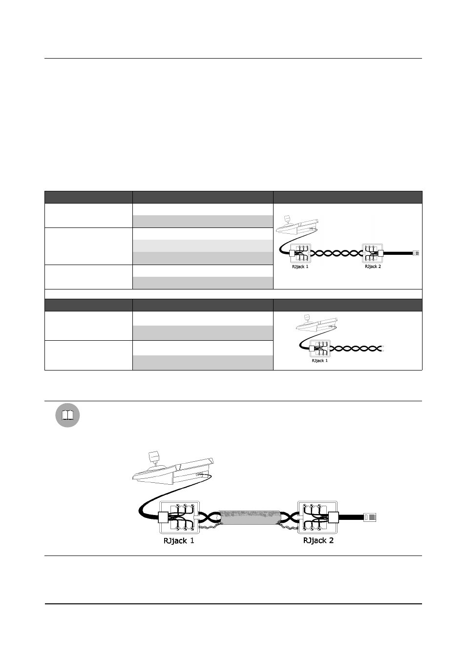
The connections are of the RS485 one-way type (two-way only for SANYO and SONY DVR/MUX) and the
maximum distance between keyboard and DVR/MUX is 1200 metres.
WARNING!!!
If, after carefully terminating the RS485 line, there are communication problems, in addition to the
two RS485A and RS485B connections, make also the third connection (using the shielded cable mesh
for example) between the keyboard chassis (RED cable in Rjjack1) and the chassis of the connected
device.
Page 60 of 176
MNVADCT03_0716