Videotec DCT User Manual
Page 152
7.4.3.3
Toolbar
This comprises 14 graphics keys. Each key is associated with a brief heading that describes the Menu function
corresponding to that key.
7.4.3.4
“Open” card
In this environment the user can load or design a customised image to be displayed when the keyboard is
switched on.
If the image is loaded from a file it must be a 320
×240 pixel, B&W bitmap.
7.4.3.5
“Service” Card
In this environment the user can load or design a customised image to be displayed when the
key is
pressed in the General Information page of the keyboard (see § 4.2.7 - System Information and service menu,
page 43).
If the image is loaded from a file it must be a 320
×240 pixel, B&W bitmap.
7.4.3.6
“Maps” card
In this environment the user can design the complete GRAPHICS environment of the keyboard, defining the
graphics appearance of the 30 maps and assigning the various function keys to them. For a more detailed
description see § 7.4.3.8 - How to design a map, page 151.
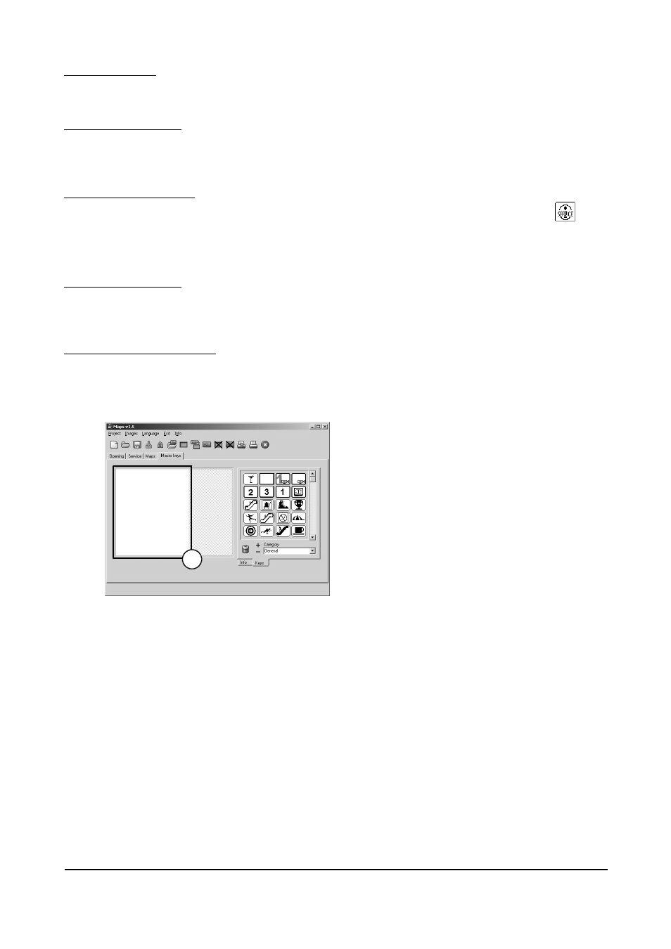
7.4.3.7
“Macro Keys” card
In this environment the operator can programme a maximum of 35 graphics keys with the same properties as
those of the maps (see § 7.4.3.8 - How to design a map, page 151). The only difference is that they cannot use
the Jump Page function because they will all be displayed on the same keyboard page once they have been
enabled (see § 4.4 - Control menu area, page 45 e § 4.2.4.6 - Common keys, page 36).
1. Area available for positioning the keys
Page 150 of 176
MNVADCT03_0716
1