15 sensormatic dome – Videotec DCT User Manual
Page 125
6.15 SENSORMATIC Dome
6.15.1
Materials and reference documents
Sensormatic Delta Dome II.
Rs-422/RS-485 Communication Protocols, 8000-2694-01, Rev. A.
6.15.2
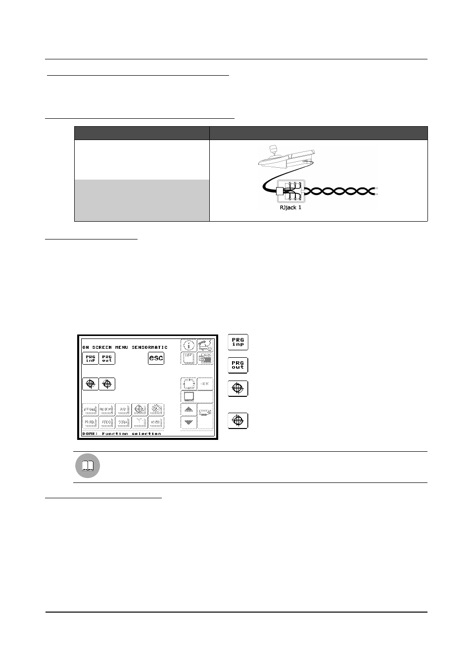
Connecting the hardware tothe dome
DCT
RJjack1
DOME
Connection diagram
RS485A
white
Rx+
RS485B
yellow
Rx-
6.15.3
Configuration
The dome is mainly configured by On Screen Menu
Some parameters can be configured by inserting a special code.
For all dome configuration operations it is necessary to enable the "Setup telemetry" FUNCTION (see §
4.2.4.5 - Functions, page 35).
Follow the general procedure to connect the dome directly to the keyboard and a monitor to the dome video
OUT (see § 6.19 - Operating procedure for setting a dome/receiver, page 137).
Go to the OSM configuration page (see § 6.1.5 - Layout of the configuration menus, page 76) where it is
possible to make the settings for the various parameters.
ENTER PROGRAMMING
To enter the dome OSM.
EXIT PROGRAMMING
To exit the dome OSM .
FOCUS NEAR
To be used as indicated in the dome handbook
(selection of submenus).
FOCUS FAR
To be used as indicated in the dome handbook
(selection of submenus).
To move within the menus use the joystick.
ZOOM is used to increase/decrease the field values and move the cursor to the left or right when
defining the text.
6.15.4
Autoflip, Focus, Iris
All these functions can be loaded by pressing the specific keys in the control menu area of the Main menu (see
§ 4.4 – Control menu area, page 45).
Refer to § 9.1 – Functions assigned to the most common graphics keys, page 164 and § 9.2.1 – Dome, page
165 to check which functions are available for the dome.
Page 123 of 176
MNVADCT03_0716