Videotec DCT User Manual
Page 58
5.3.1
ENEO video matrixes
5.3.1.1
EKR-8/4, EKR-16/4, EKR-32/8 models
5.3.1.1.1
Connection and operational test
The standard communication cable is used (see § 3.3 - One keyboard per line: standard connection cable,
page 15).
Set the DIP switch appropriately inside the matrix (all DIPs OFF: Macro protocol, baud rate 38400,
programming disabled).
On completing the connection it should be immediately possible to switch the input videos using the
video/telemetry controls.
5.3.1.1.2
Matrix setup
The matrix can be set up via the corresponding menu (see § 5.3.4.1 - Macro OSM, page 58).
5.3.1.2
VKR-16/4, VKR-32/8 models
5.3.1.2.1
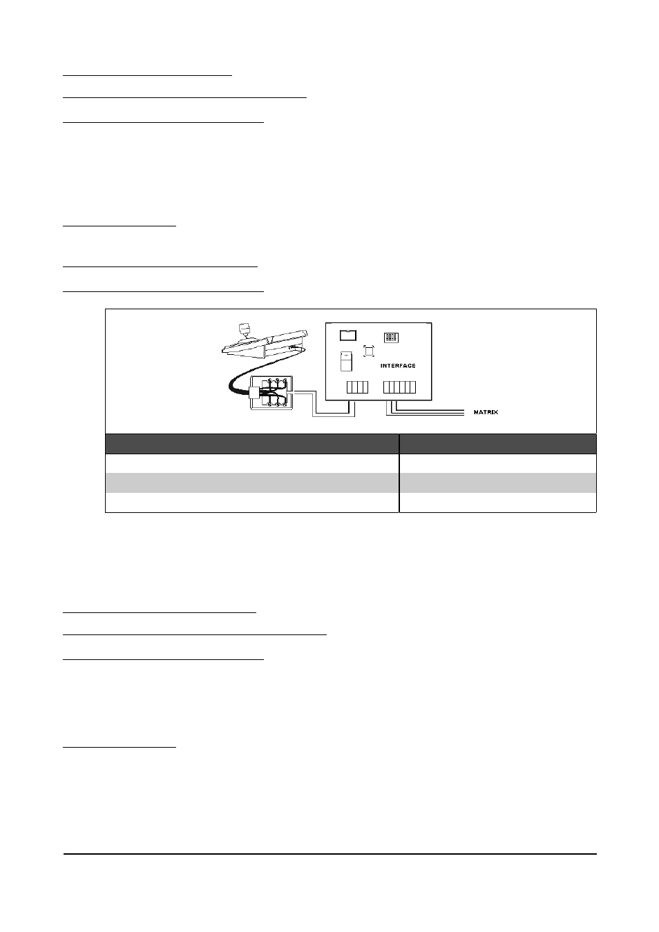
Connection and operational test
The connection diagram is as follows:
DCT
RJjack
Interface IN
Interface OUT
Matrix
RS485A
white
A
RX
TX
--
--
--
TX
RX
RS485B
yellow
B
GND
GND
In the matrix, set the communication protocol for port 3 (RS232 PC) as follows:
baud rate: 9600, parity: none, protocol: PC, number of characters: 8.
On completing the connection it should be immediately possible to switch the input videos using the
video/telemetry controls.
Only VKR-KB1 or VKR-KB2 ENEO type keyboards can be used for matrix setup.
5.3.2
VIDEOTEC video matrixes
5.3.2.1
SM42A
, SM82A
, SM84A
, SM164A
models
5.3.2.1.1
Connection and operational test
The standard communication cable is used (see § 3.3 - One keyboard per line: standard connection cable,
page 15). Set the DIP switch appropriately inside the matrix (all DIPs OFF: Macro protocol, baud rate 38400,
programming disabled).
On completing the connection it should be immediately possible to switch the input videos using the
video/telemetry controls.
5.3.2.1.2
Matrix setup
The matrix can be set up via the corresponding menu (see § 5.3.4.1 - Macro OSM, page 58).
Page 56 of 176
MNVADCT03_0716