Videotec DCT User Manual
Page 15
3 COMMUNICATION LINES AND CONNECTIONS
3.1 Video line and telemetry lines
The DTC keyboard can be used to control a wide range of products, for both video control (video matrixes,
video multiplexers and DVR's) and telemetry control (receivers or domes). It is therefore necessary to define
the system structure at the keyboard level so as to achieve efficient communication between the connected
devices.
By “Video line” we mean the communication channel intended to control the video device; “telemetry line”
refers to the two channels available for telemetry control.
We advise starting first with the “VIDEO line” configuration and then the configuration of the
“TELEMETRY lines”.
3.1.1
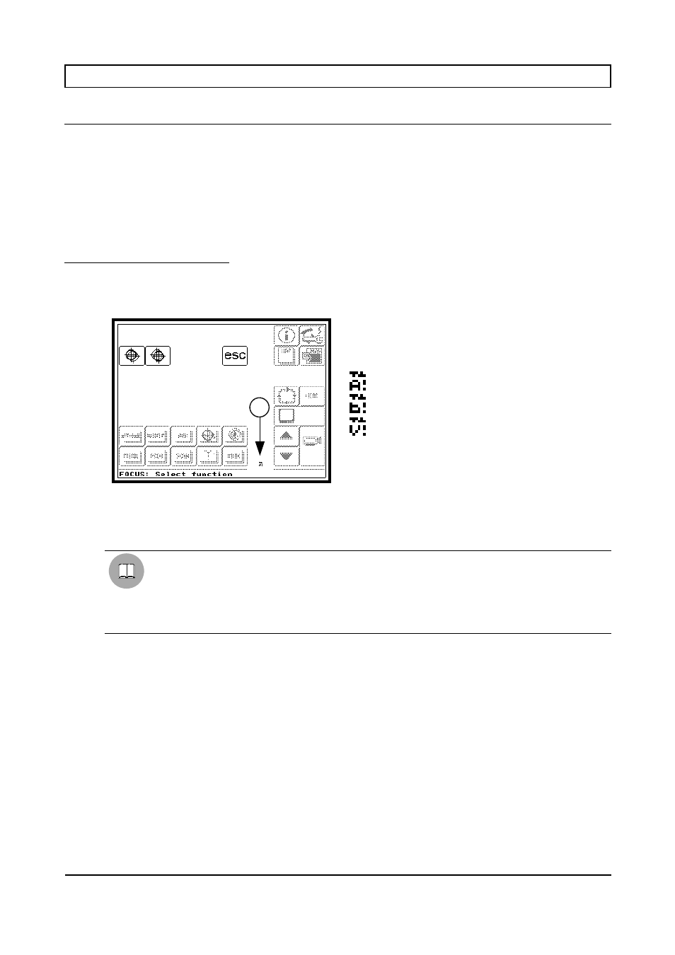
Line busy indicators
Whenever a line is busy due to transmission of a video or telemetry control, a small symbol will appear on the
display for the duration of the transmission, in the position shown in the illustration, to identify the line being
used (Telemetry A/B or Video).
1. Symbol identifying the line being used
Telemetry Line A busy
Telemetry Line B busy
Video Line busy.
If the line jams for some reason during transmission of the control, the identification symbol will remain on
the screen to give an initial indication regarding the fault.
WARNING
•
While the keyboard is operating correctly, the line busy indicators will only be visible when
using protocols with very low baud rates.
•
If working in the GRAPHICS environment (see § 4.6 - GRAPHICS Environment Area, page
50), avoid placing graphics keys on top of the indicators: this may partially delete the key itself
after the first command has been sent.
Page 13 of 176
MNVADCT03_0716
1