4 el.mo. dome – Videotec DCT User Manual
Page 88
6.4 EL.MO. Dome
6.4.1
Materials and reference documents
El.Mo. D7720B-J1P Dome.
Surveillance Control Protocol (DSCP), ver2.4, 2001.05.25.
6.4.2
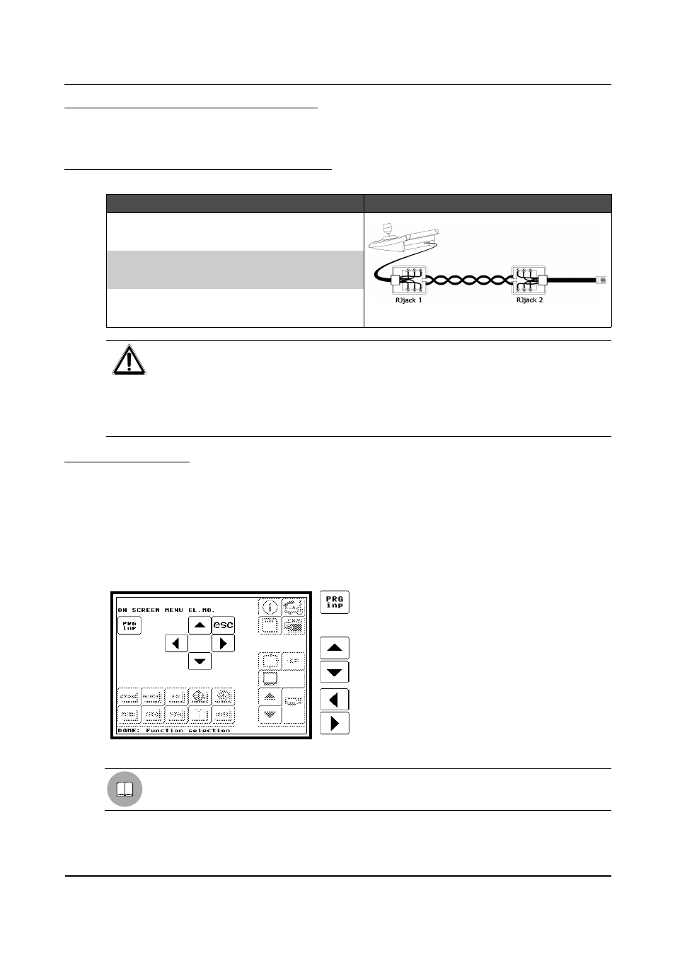
Connecting the hardware to the dome
DCT
RJjack1
RJjack2
DOME
Connection diagram
RS485A
white
red
RS485A
GND
red
green
GND
RS485B
yellow
black
RS485B
WARNING
For both telephone cables (the one connected to the keyboard and also the one connected to the
dome) you must use those supplied as accessories to the keyboard!
DO NOT USE the grey telephone cable supplied with the El.Mo dome. Using the grey cable (with
the consequent pin connection error shown in the diagram) may damage the keyboard, because
the dome also supplies 12VDC power along the RJ11 connector as well as the usual RS485
signals.
6.4.3
Configuration
The dome is mainly configured by On Screen Menu
Some parameters can be configured by inserting a special code.
For all dome configuration operations it is necessary to enable the "Setup telemetry" FUNCTION (see §
4.2.4.5 - Functions, page 35).
Follow the general procedure to connect the dome directly to the keyboard and a monitor to the dome video
OUT (see § 6.19 - Operating procedure for setting a dome/receiver, page 137).
Go to the page for OSM dome configuration (see § 6.1.5 - Layout of the configuration menus, page 76) where
it is possible to make the settings for the various dome parameters.
ENTER / EXIT PROGRAMMING AND
CONFIRM “ENTER”
To enter the dome OSM and submenus.
UP/DOWN ARROWS
To move within the dome menus.
LEFT/RIGHT ARROWS
To change the value indicated by the cursor.
When required, Zoom Tele and Zoom Wide are activated by rotating the joystick.
See the dome handbook for the correct parameter settings.
Page 86 of 176
MNVADCT03_0716