Videotec DCT User Manual
Page 173
10.2.2.2
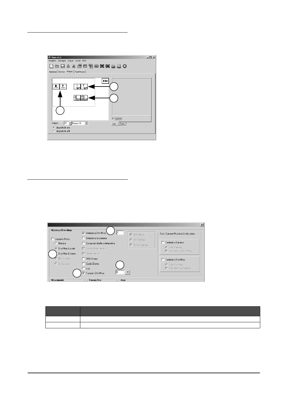
Defining page No. 30 in the maps
In page No. 30 we insert the 6 buttons (taken from the library) as described above, arranging them so that they
are divided into three groups located inside the Device area. We also insert a “return to page No. 1” button,
which must be placed outside the Device area.
1. Group 1
2. Group 2
3. Group 3
The keys in the 3 groups have the following characteristics:
Group 1
Direct function-type control.
Group 2
Video switching control.
Group 3
Function-type control + video switching control.
10.2.2.3
Group 1 – Function-type controls
We associate the various parameter values with each of the two buttons, following the sequence shown in the
illustration:
1. Select “Local DVR/MUX”;
2. Select “Select DVR/MUX” and insert the address of the device (1 in this case);
3. Select “DVR/MUX functions”;
4. Insert the number of the function (between 0 and 127) to be associated with the key.
Selecting a function-type
control
In this example the Stop function key (button 1) will be assigned the value 0, while the Play function key
(button 2) will be assigned the value 1.
These are the controls that will be transmitted from the keyboard when the keys are pressed:
BUTTON
CONTROL
1
[VA0KB1FreM0,1I]
2
[VA0KB1FreM1,1J]
Page 171 of 176
MNVADCT03_0716
1
2
3
1
2
3
4