Dte and dce communication, Comm port communication modes – Teledyne GFC-7000E - Trace CO2 Analyzer User Manual
Page 96
Model GFC7000E Instruction Manual
Operating Instructions
04584 Rev A1
85
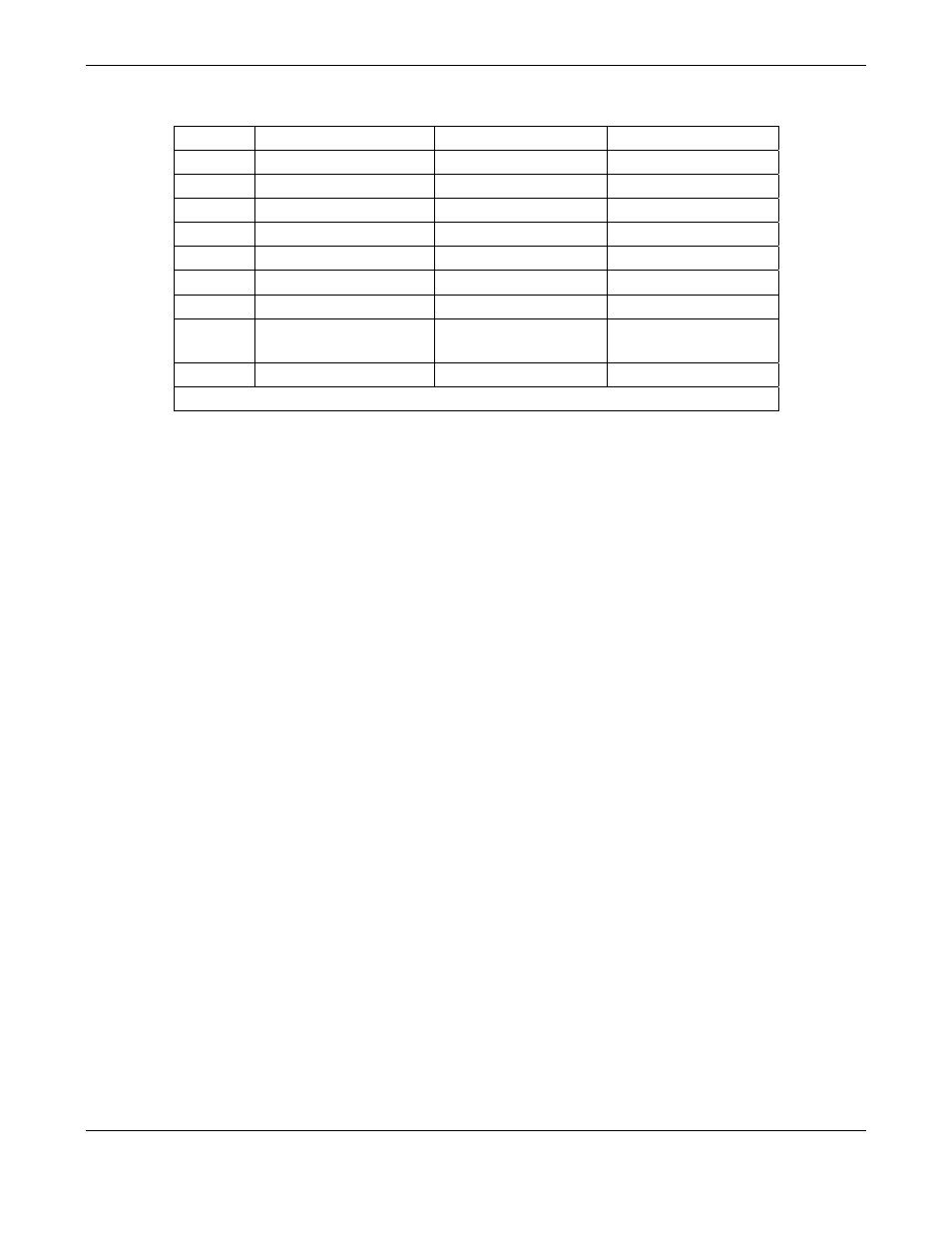
Table 6-15: COM1 and COM2 DB-9 Pin Assignments
Pin #
COM1 (RS-232)
COM2 (RS-232)
COM2 (RS-485)
1
Not used
Not used
Not used
2
Transmit Data*
Receive Data
DATA -
3
Receive Data*
Transmit Data
Data +
4
Not used
Not used
Not used
5
Signal Ground
Signal Ground
Signal Ground
6
Not used
Not used
Not used
7
DATA SET READY*
DATA SET READY
Not used
8
REQUEST TO SEND*
(=DTE Ready)
REQUEST TO SEND
Not used
9
Not used
Not used
Not used
* Configurable for COM1 at rear panel using the DTE-DCE switch
6.10.5. DTE and DCE Communication
RS-232 was developed for allowing communications between data terminal equipment (DTE) and
data communication equipment (DCE). Basic terminals always fall into the DTE category whereas
modems are always considered DCE devices. The difference between the two is the pin
assignment of the Data Receive and Data Transmit functions. DTE devices receive data on pin 2
and transmit data on pin 3, DCE devices receive data on pin 3 and transmit data on pin 2.
To allow the analyzer to be used with terminals (DTE), modems (DCE) and computers (which can
be either), a switch mounted below the serial ports on the rear panel allows the user to switch
between the two functions.
6.10.6. COMM Port Communication Modes
Each of the analyzer’s serial ports can be configured to operate in a number of different modes,
listed in Table 6-16, which can be combined by adding the mode ID numbers. For example, quiet
mode, computer mode and internet-enabled mode would carry a combined mode ID of 11, the
standard configuration on the MGFC7000E COM2 port. Note that each COM port needs to be
configured independently.