Teledyne GFC-7000E - Trace CO2 Analyzer User Manual
Page 25
Model GFC7000E Instruction Manual
Getting Started
04584 Rev A1
14
The pin assignments for the status outputs can be found in the table below:
Table 3-2: GFC7000E Status Output Pin Outs
Output #
Status
Definition
Condition
1
SYSTEM OK
On if no faults are present.
2
CONC VALID
On if CO
2
concentration measurement is valid.
If the CO
2
concentration measurement is invalid, this bit is OFF.
3
HIGH RANGE
On if unit is in high range of DUAL or AUTO range modes.
4
ZERO CAL
On whenever the instruments ZERO point is being calibrated.
5
SPAN CAL
On whenever the instruments SPAN point is being calibrated.
6
DIAG MODE
On whenever the instrument is in DIAGNOSTIC mode.
7
ALARM1
On whenever the measured CO
2
concentration is above the set
point for ALM1
8 ALARM2
On whenever the measured CO
2
concentration is above the set
point for ALM2
D
EMITTER BUSS The emitters of the transistors on pins 1-8 are bussed together.
+
DC POWER
+ 5 VDC
Digital Ground
The ground level from the analyzer’s internal DC power supplies.
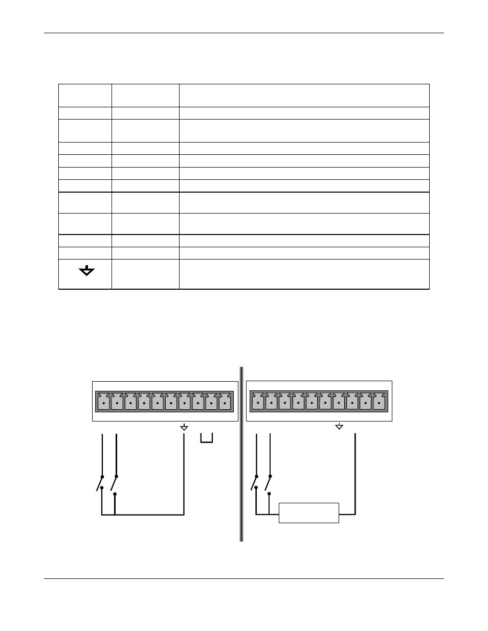
11. If you wish to use the analyzer’s to remotely activate the zero and span calibration modes,
several digital control inputs are provided via a 10-pin connector labeled CONTROL IN on the
analyzer’s rear panel. Two methods for energizing the inputs are provided below; the first
using the internal +5V available on the CONTROL IN connector and the second, if an external,
isolated supply is employed.
CONTROL IN
A B C D E F U +
S
P
A
N
Z
E
R
O
CONTROL IN
A B C D E F U +
-
+
5 VDC Power
Supply
S
P
A
N
Z
E
R
O
Local Power Connections
External Power Connections