Model, Gfc7000e – Teledyne GFC-7000E - Trace CO2 Analyzer User Manual
Page 27
Model GFC7000E Instruction Manual
Getting Started
04584 Rev A1
16
CAUTION
In order to prevent dust from getting into the gas flow channels of your analyzer, it was
shipped with small plugs inserted into each of the pneumatic fittings on the back panel.
Make sure that all of these dust plugs are removed before attaching
exhaust and supply gas lines.
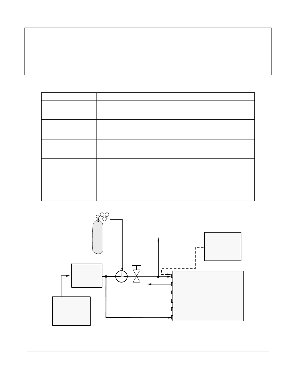
Table 3-4: Model GFC7000E Rear Panel Pneumatic Connections
Rear Panel Label
Function
SAMPLE
Connect a gas line from the source of sample gas here.
Calibration gasses are also inlet here on units without
zero/span/shutoff valve or IZS options installed.
EXHAUST
Connect an exhaust gas line of not more than 10 meters long here.
PRESSURE SPAN
On units with zero/span/shutoff valve options installed, connect a
gas line to the source of calibrated span gas here.
VENT SPAN
Span gas vent outlet for units with zero/span/shutoff valve options
installed.
Connect an exhaust gas line of not more than 10 meters long here.
IZS
Internal zero air scrubber.
on units with zero/span/shutoff valve options installed but NO
internal zero air scrubber, attach a gas line to the source of zero air
here.
PURGE IN
This inlet supplies purge air to the GFC wheel housing (see section
10.2.2)
Connect a source of dried air that has been scrubbed of CO
2
.
VENT
Calibrated CO
2
gas at desired
span gas
concentration
Source of
SAMPLE Gas
Removed
during
Calibration
Valve
Needle
valve to
control
flow
MODEL
GFC7000E
Sample
IZS
Exhaust
Vent Span
Pressure Span
Purge In
Indicating
soda-lime
MODEL 701
Zero Air
Generator
Figure 3-3: Pneumatic Connections–Basic Configuration–Using Bottled Span Gas