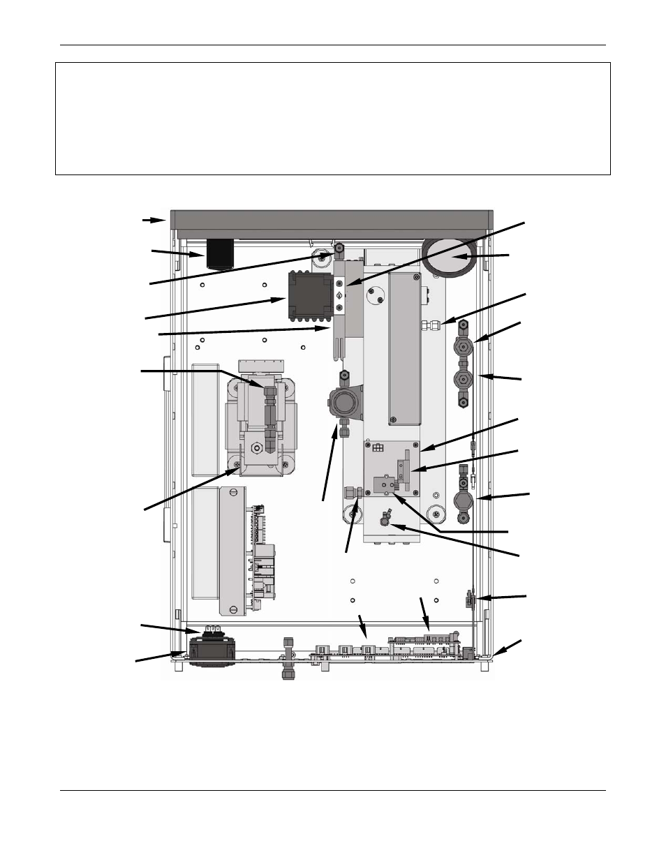
Figure 3-11: assembly layout – Teledyne GFC-7000E - Trace CO2 Analyzer User Manual
Page 41
Model GFC7000E Instruction Manual
Getting Started
04584 Rev A1
30
NOTE
Once you have completed the above set-up procedures, please fill out the Quality
Questionnaire that was shipped with your unit and return it to Teledyne Instruments.
This information is vital to our efforts in continuously improving our service and our
products.
THANK YOU.
Particulate Filter
SY
N
C
/DEM
O
D
B
O
A
R
D
GFC Motor
On/Off Switch &
Circuit Breaker
PS1
(+
5
V
D
C;
±
15V
D
C
)
PS
2
(+1
2
VD
C
)
GFC Wheel Housing
& IR Source Heat
Rel
a
y Bo
a
rd
Optional
Zero/Span
Valve
OPTIC
A
L B
E
NC
H
Sample Gas
Critical
Flow Orifice
Front Panel
Rear Panel
CPU Card
Mother
Board
Power
Receptacle
Optional
Sample/Cal
Valve
Optional
Shutoff
Valve
Gas Flow
Sensor Assy
IR Source
Pump Assy
Fan
Optical Bench
Gas Outlet
Sample Gas
Pressure Sensor
Flow Sensor
Optical Bench
Gas Inlet
Sample Gas
Temperature
Sensor
GFC Wheel
Housing Purge
Gas Inlet & Flow
Control Orifice
Purge Gas
Pressure
Control Assy
Optional
Ethernet Card
Figure 3-11: Assembly Layout
- 1220 - Multipoint flammable gas and vapor detection system (50 pages)
- 212R - Thermal conductivity analyzer (28 pages)
- 235 - Thermal conductivity analyzer (38 pages)
- 275R - Portable turbine generator purge gas analyzer (21 pages)
- 2000A-EU - General purpose thermal conductivity analyzer (86 pages)
- 2000XTC - Thermal conductivity analyzer (40 pages)
- 2010A - Split architecture thermal conductivity analyzer (110 pages)
- 2010B - Split architecture thermal conductivity analyzer (98 pages)
- 2020 - Explosion proof thermal conductivity analyzer (80 pages)
- 2120 - Trace Nitrogen in Argon Analyzer (66 pages)
- 2120XL - Trace Nitrogen Analyzer (85 pages)
- 2230R - Process Hydrogen Analyzer (26 pages)
- 2240 – Portable Handheld Hydrogen Leak Detector, 3rd generation (updated 1/31/11) (30 pages)
- 2240 - Portable Handheld Hydrogen Leak Detector, 3rd generation (revision 2/29/08) (40 pages)
- 2240 – Portable Handheld Hydrogen Leak Detector, 2nd generation (13 pages)
- 2750 - Portable turbine generator gas analzyer (40 pages)
- 300P - Percent oxygen analyzer (24 pages)
- 306WA - Analog trace oxygen analyzer (46 pages)
- 311 - Portable trace oxygen analyzer (19 pages)
- 311D - Portable trace oxygen analyzer with digital meter (18 pages)
- 311XL - Portable trace oxygen analyzer (18 pages)
- 316RA / RB / RAD / RBD - Oxygen analyzers (24 pages)
- 319R - Oxygen analyzer (23 pages)
- 320 Series - Portable oxygen detectors (24 pages)
- 326, 327 and 328 - Oxygen analyzers (45 pages)
- 329R - Oxygen analyzer (22 pages)
- 335 - Analog control room monitor for personnel safety (24 pages)
- 356WA - Analog trace oxygen analyzer (42 pages)
- 3000MA - Paramagnetic oxygen analyzer (63 pages)
- 3000MA - Paramagnetic oxygen analyzer Addendum (2 pages)
- 3000MB - Paramagnetic oxygen analyzer (59 pages)
- 3000PA - General purpose percent oxygen analyzer (69 pages)
- 3000PAEU - General purpose percent oxygen analyzer (78 pages)
- 3000PB - Bulkhead mount percent oxygen analyzer (82 pages)
- 3000TA - General purpose trace oxygen analyzer (75 pages)
- 3000TA-EU - General purpose trace oxygen analyzer (89 pages)
- 3000TA-XLEU - Trace oxygen analyzer (108 pages)
- 3000TB - Bulkhead mount trace oxygen analyzer (78 pages)
- 3000TB-XL - Trace oxygen analyzer (78 pages)
- 3000ZA - Trace oxygen analyzer (81 pages)
- 3000ZA-3X - Trace oxygen analyzer (72 pages)
- 3000ZA2G - Zirconium oxide analyzer (72 pages)
- 3000 Ultra Trace - PPB oxygen analyzer (72 pages)
- 3010MA - Paramagnetic oxygen analyzer, includes 0-100% range (88 pages)
- 3010MA – Paramagnetic oxygen analyzer, no 0-100% range – (superceded) (88 pages)