Teledyne GFC-7000E - Trace CO2 Analyzer User Manual
Page 252
Model 360E Instruction Manual
APPENDIX A-4: MGFC7000E Signal I/O Definitions, Revision E.0
045840110 Rev B.3
241
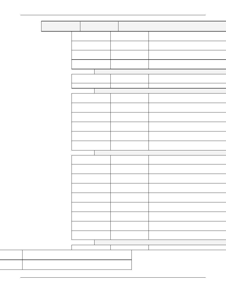
SIGNAL NAME
BIT OR CHANNEL
NUMBER
DESCRIPTION
ST_SPAN_CAL
4
0 = in span calibration
1 = not in span
ST_DIAG_MODE
5
0 = in diagnostic mode
1 = not in diagnostic mode
ST_CONC_ALARM_1
2
6
0 = conc. limit 1 exceeded
1 = conc. OK
ST_CONC_ALARM_2
2
7
0 = conc. limit 2 exceeded
1 = conc. OK
B status outputs, U27, J1018, pins 1–8 = bits 0–7, default I/
ST_AUTO_REF
2, 3
0
0 = in auto-reference mode
1 = not in auto-reference mode
1–7
Spare
Front panel I
2
C keyboard, default I
2
C address 4
MAINT_MODE
5 (input)
0 = maintenance mode
1 = normal mode
LANG2_SELECT
6 (input)
0 = select second language
1 = select first language (English)
SAMPLE_LED
8 (output)
0 = sample LED on
1 = off
CAL_LED
9 (output)
0 = cal. LED on
1 = off
FAULT_LED
10 (output)
0 = fault LED on
1 = off
AUDIBLE_BEEPER
14 (output)
0 = beeper on (for diagnostic testing only)
1 = off
Relay board digital output (PCF8574), default I
2
C add
RELAY_WATCHDOG
0
Alternate between 0 and 1 at least every 5 se
relay board active
WHEEL_HTR
1
0 = wheel heater on
1 = off
BENCH_HTR
2
0 = optical bench heater on
1 = off
O2_CELL_HEATER
5
3
0 = O
2
sensor cell heater on
1 = off
CAL_VALVE
4
0 = let cal. gas in
1 = let sample gas in
SPAN_VALVE
5
0 = let span gas in
1 = let zero gas in
ZERO_SCRUB_VALV
E
2
6
0 = open zero scrubber valve
1 = close
SHUTOFF_VALVE
6
0 = energize shutoff valve
1 = de-energize
IR_SOURCE_ON
7
0 = IR source on
1 = off
Rear board primary MUX analog inputs
SAMPLE_PRESSURE 0 Sample
pressure
1
Vacuum pressure
1
Purge pressure