Front panel interface, Analyzer status led’s, Figure 10-16: interface block diagram – Teledyne GFC-7000E - Trace CO2 Analyzer User Manual
Page 186
Model GFC7000E Instruction Manual
THEORY OF OPERATION
04584 Rev A1
175
Mother
Board
Status Outputs:
1 – 8
Control Inputs:
1 – 6
CPU
RS–232 ONLY
RS-232 or RS–485
KEYBOARD
RELAY
BOARD
PC/104 BUS
FRONT PANEL DISPLAY
I
2
C BUS
I
2
C BUS
Analog Outputs
A1
A2
A3
Optional
4-20 mA
COMM B
Female
A4
ST
COMM A
Male
ETHERNET
OPTION
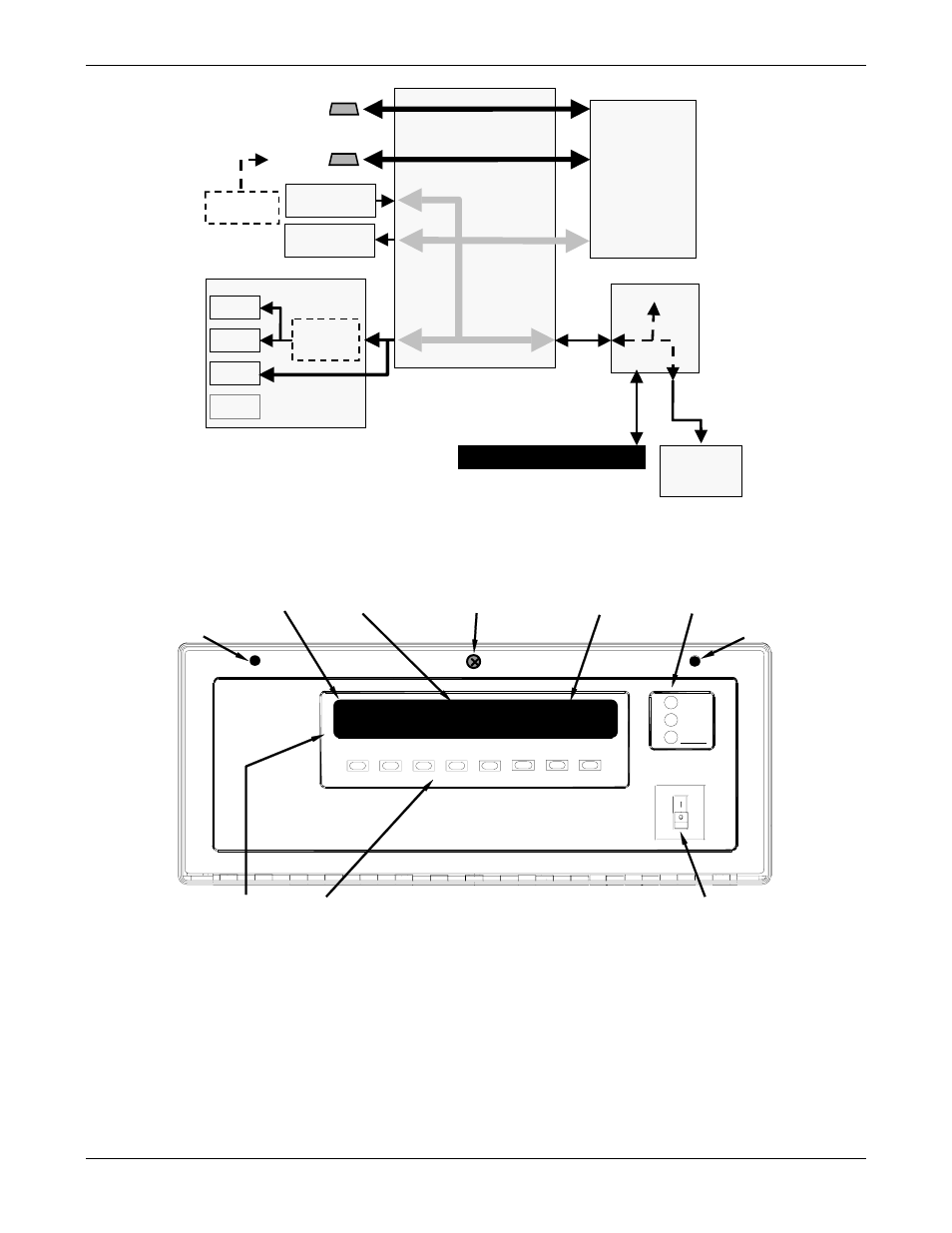
Figure 10-16: Interface Block Diagram
10.4.1. Front Panel Interface
MODE FIELD
KEY DEFINITIONS
MESSAGE FIELD
CONCENTRATION FIELD STATUS LED’s
KEYBOARD
ON / OFF SWITCH
FASTENER
FASTENER
POWER
FAULT
CAL
SAMPLE
GAS FILTER CORRELATION CO
2
ANALYZER- MODEL GFC7000E
SAMPLE A
RANGE = 500.0 PPM
CO2 = 400.0
TST> CAL
SETUP
LOCKING SCREW
Figure 10-17: GFC7000E Front Panel Layout
The most commonly used method for communicating with the MGFC7000E Analyzer is via the
instrument’s front panel which includes a set of three status LEDs, a vacuum florescent display
and a keyboard with 8 context sensitive keys.
10.4.1.1. Analyzer Status LED’s
Three LEDS are used to inform the user of the instruments basic operating status
- 1220 - Multipoint flammable gas and vapor detection system (50 pages)
- 212R - Thermal conductivity analyzer (28 pages)
- 235 - Thermal conductivity analyzer (38 pages)
- 275R - Portable turbine generator purge gas analyzer (21 pages)
- 2000A-EU - General purpose thermal conductivity analyzer (86 pages)
- 2000XTC - Thermal conductivity analyzer (40 pages)
- 2010A - Split architecture thermal conductivity analyzer (110 pages)
- 2010B - Split architecture thermal conductivity analyzer (98 pages)
- 2020 - Explosion proof thermal conductivity analyzer (80 pages)
- 2120 - Trace Nitrogen in Argon Analyzer (66 pages)
- 2120XL - Trace Nitrogen Analyzer (85 pages)
- 2230R - Process Hydrogen Analyzer (26 pages)
- 2240 – Portable Handheld Hydrogen Leak Detector, 3rd generation (updated 1/31/11) (30 pages)
- 2240 - Portable Handheld Hydrogen Leak Detector, 3rd generation (revision 2/29/08) (40 pages)
- 2240 – Portable Handheld Hydrogen Leak Detector, 2nd generation (13 pages)
- 2750 - Portable turbine generator gas analzyer (40 pages)
- 300P - Percent oxygen analyzer (24 pages)
- 306WA - Analog trace oxygen analyzer (46 pages)
- 311 - Portable trace oxygen analyzer (19 pages)
- 311D - Portable trace oxygen analyzer with digital meter (18 pages)
- 311XL - Portable trace oxygen analyzer (18 pages)
- 316RA / RB / RAD / RBD - Oxygen analyzers (24 pages)
- 319R - Oxygen analyzer (23 pages)
- 320 Series - Portable oxygen detectors (24 pages)
- 326, 327 and 328 - Oxygen analyzers (45 pages)
- 329R - Oxygen analyzer (22 pages)
- 335 - Analog control room monitor for personnel safety (24 pages)
- 356WA - Analog trace oxygen analyzer (42 pages)
- 3000MA - Paramagnetic oxygen analyzer (63 pages)
- 3000MA - Paramagnetic oxygen analyzer Addendum (2 pages)
- 3000MB - Paramagnetic oxygen analyzer (59 pages)
- 3000PA - General purpose percent oxygen analyzer (69 pages)
- 3000PAEU - General purpose percent oxygen analyzer (78 pages)
- 3000PB - Bulkhead mount percent oxygen analyzer (82 pages)
- 3000TA - General purpose trace oxygen analyzer (75 pages)
- 3000TA-EU - General purpose trace oxygen analyzer (89 pages)
- 3000TA-XLEU - Trace oxygen analyzer (108 pages)
- 3000TB - Bulkhead mount trace oxygen analyzer (78 pages)
- 3000TB-XL - Trace oxygen analyzer (78 pages)
- 3000ZA - Trace oxygen analyzer (81 pages)
- 3000ZA-3X - Trace oxygen analyzer (72 pages)
- 3000ZA2G - Zirconium oxide analyzer (72 pages)
- 3000 Ultra Trace - PPB oxygen analyzer (72 pages)
- 3010MA - Paramagnetic oxygen analyzer, includes 0-100% range (88 pages)
- 3010MA – Paramagnetic oxygen analyzer, no 0-100% range – (superceded) (88 pages)