Sample chamber – Teledyne GFC-7000E - Trace CO2 Analyzer User Manual
Page 50
Model GFC7000E Instruction Manual
Optional Hardware and Software
04584 Rev A1
39
The state of the zero/span valves can also be controlled:
• Manually from the analyzer’s front panel by using the SIGNAL I/O controls located under
the DIAG Menu (Section 6.9.2),
• By activating the instrument’s AutoCal feature (Section 7.6),
• Remotely by using the external digital control inputs (Section 6.13.1.2 and Section 7.5.2),
or
• Remotely through the RS-232/485 serial I/O ports (see Appendix A-6 for the appropriate
commands).
FLOW / PRESSURE
SAMPLE
SENSOR PCA
PRESSURE
SENSOR
FLOW
SENSOR
INSTRUMENT CHASSIS
PUMP
SAMPLE CHAMBER
VENT SPAN
OUTLET
PRESSURE
SPAN INLET
IZS INLET
EXHAUST GAS
OUTLET
PURGE GAS
INLET
SAMPLE GAS
INLET
S
a
m
p
le
G
a
s
C
ri
tic
a
l
Fl
ow
O
rif
ic
e
GFC Wheel
Motor
GFC Motor
Heat Sync
GFC Wheel
Housing
Purge Gas
Pressure
Control Assy
PARTICULATE
FILTER
SHUT OFF
VALVE
1
2
SAMPLE /CAL
VALVE
3
2
1
Purge Gas
Flow Control
Orifice
ZERO/SPAN
VALVE
2
1
3
ex
te
rn
a
l C
O
2
S
c
ru
bbe
r
(O
pt 5
3
O
n
ly
)
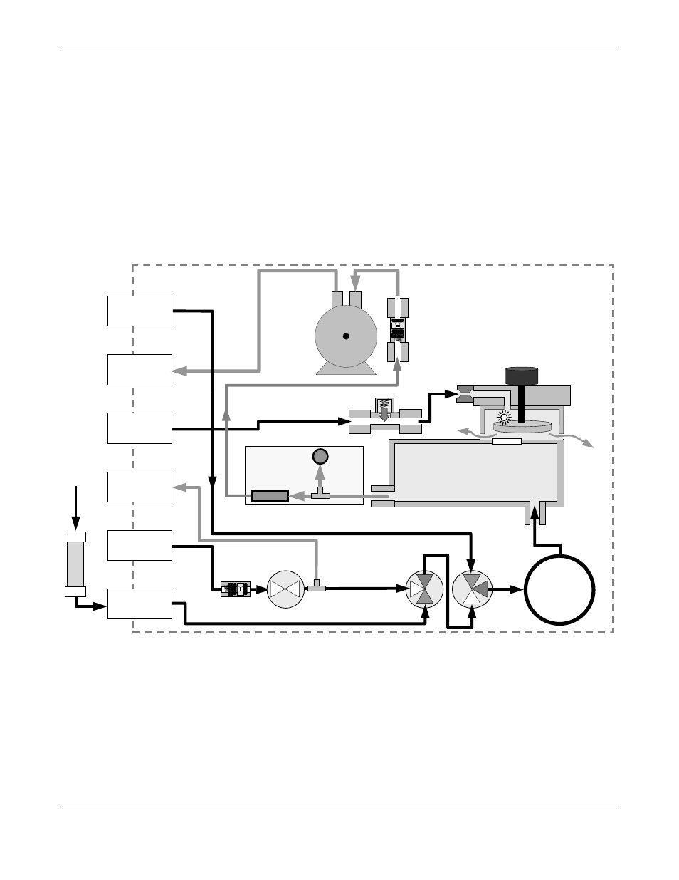
Figure 5-2: Internal Pneumatic Flow – Zero/Span/Shutoff Valves OPT 50 & 51
- 1220 - Multipoint flammable gas and vapor detection system (50 pages)
- 212R - Thermal conductivity analyzer (28 pages)
- 235 - Thermal conductivity analyzer (38 pages)
- 275R - Portable turbine generator purge gas analyzer (21 pages)
- 2000A-EU - General purpose thermal conductivity analyzer (86 pages)
- 2000XTC - Thermal conductivity analyzer (40 pages)
- 2010A - Split architecture thermal conductivity analyzer (110 pages)
- 2010B - Split architecture thermal conductivity analyzer (98 pages)
- 2020 - Explosion proof thermal conductivity analyzer (80 pages)
- 2120 - Trace Nitrogen in Argon Analyzer (66 pages)
- 2120XL - Trace Nitrogen Analyzer (85 pages)
- 2230R - Process Hydrogen Analyzer (26 pages)
- 2240 – Portable Handheld Hydrogen Leak Detector, 3rd generation (updated 1/31/11) (30 pages)
- 2240 - Portable Handheld Hydrogen Leak Detector, 3rd generation (revision 2/29/08) (40 pages)
- 2240 – Portable Handheld Hydrogen Leak Detector, 2nd generation (13 pages)
- 2750 - Portable turbine generator gas analzyer (40 pages)
- 300P - Percent oxygen analyzer (24 pages)
- 306WA - Analog trace oxygen analyzer (46 pages)
- 311 - Portable trace oxygen analyzer (19 pages)
- 311D - Portable trace oxygen analyzer with digital meter (18 pages)
- 311XL - Portable trace oxygen analyzer (18 pages)
- 316RA / RB / RAD / RBD - Oxygen analyzers (24 pages)
- 319R - Oxygen analyzer (23 pages)
- 320 Series - Portable oxygen detectors (24 pages)
- 326, 327 and 328 - Oxygen analyzers (45 pages)
- 329R - Oxygen analyzer (22 pages)
- 335 - Analog control room monitor for personnel safety (24 pages)
- 356WA - Analog trace oxygen analyzer (42 pages)
- 3000MA - Paramagnetic oxygen analyzer (63 pages)
- 3000MA - Paramagnetic oxygen analyzer Addendum (2 pages)
- 3000MB - Paramagnetic oxygen analyzer (59 pages)
- 3000PA - General purpose percent oxygen analyzer (69 pages)
- 3000PAEU - General purpose percent oxygen analyzer (78 pages)
- 3000PB - Bulkhead mount percent oxygen analyzer (82 pages)
- 3000TA - General purpose trace oxygen analyzer (75 pages)
- 3000TA-EU - General purpose trace oxygen analyzer (89 pages)
- 3000TA-XLEU - Trace oxygen analyzer (108 pages)
- 3000TB - Bulkhead mount trace oxygen analyzer (78 pages)
- 3000TB-XL - Trace oxygen analyzer (78 pages)
- 3000ZA - Trace oxygen analyzer (81 pages)
- 3000ZA-3X - Trace oxygen analyzer (72 pages)
- 3000ZA2G - Zirconium oxide analyzer (72 pages)
- 3000 Ultra Trace - PPB oxygen analyzer (72 pages)
- 3010MA - Paramagnetic oxygen analyzer, includes 0-100% range (88 pages)
- 3010MA – Paramagnetic oxygen analyzer, no 0-100% range – (superceded) (88 pages)