Status outputs, Control inputs – remote zero, span – Teledyne GFC-7000E - Trace CO2 Analyzer User Manual
Page 216
Model GFC7000E Instruction Manual
TROUBLESHOOTING & REPAIR PROCEDURES
04584 Rev A1
205
described in Section 6.9.4.2 and then perform an Analog Output Step Test as described in Section
6.9.3.
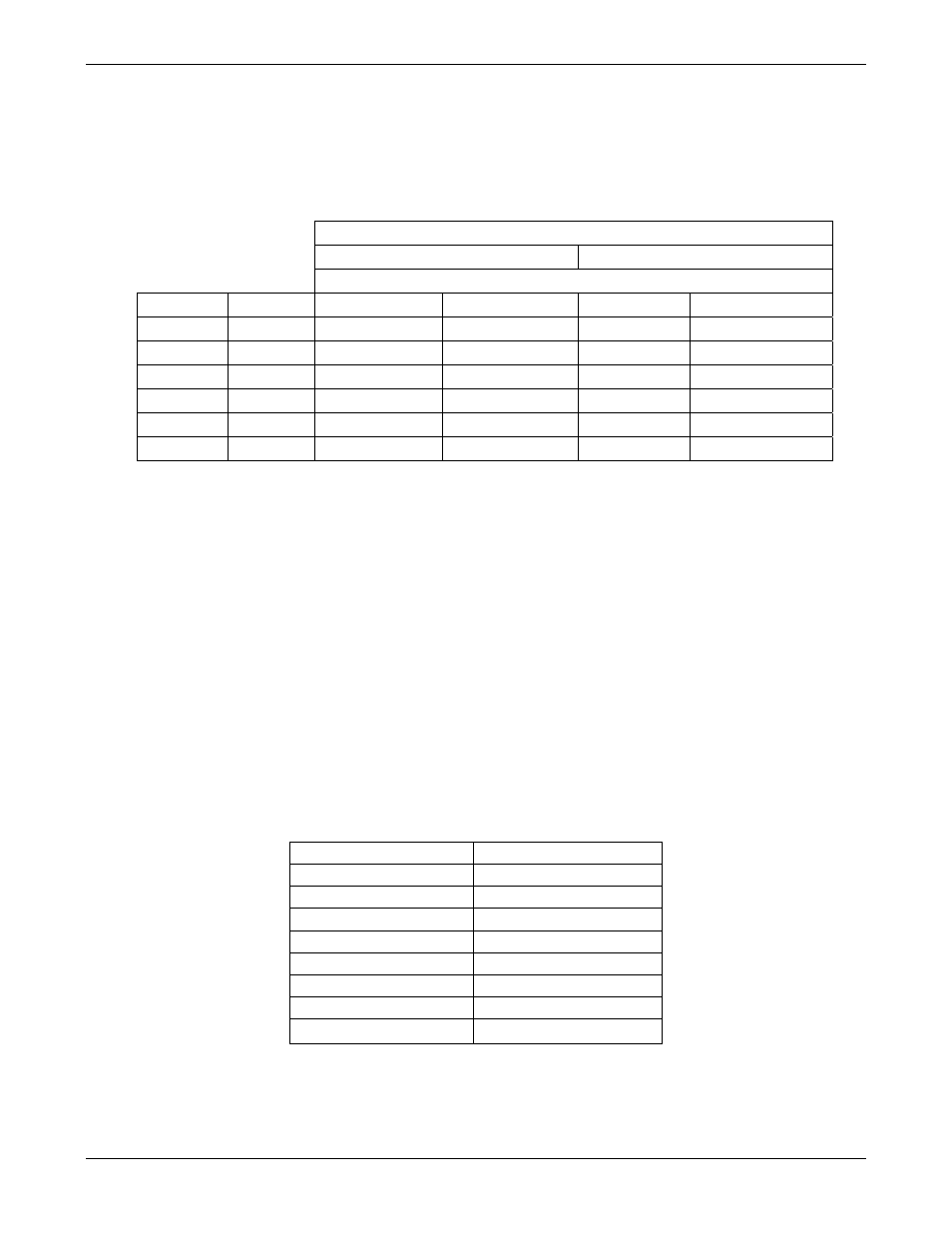
For each step the output should be within 1% of the nominal value listed in the table below.
Table 11-11: Analog Output Test Function - Nominal Values Current Outputs
OUTPUT RANGE
2 -20
4 -20
NOMINAL OUTPUT VALUES
STEP
%
CURRENT
V(250 OHMS)
CURRENT
V(250 OHMS)
1 0 2
mA 0.5V
4
1
2 20 5.6
1.4
7.2
1.8
3 40 9.2
2.3
10.4
2.6
4 60 12.8
3.2
13.6
3.4
5 80 16.4
4.1
16.8
4.2
6 100 20
5
20
5
11.4.7.4. Status Outputs
The procedure below can be used to test the Status outputs:
Connect a jumper between the “D“ pin and the “V” pin on the status output connector.
Connect a 1000 ohm resistor between the “+” pin and the pin for the status output that is being
tested.
Connect a voltmeter between the “V” pin and the pin of the output being tested (see table
below).
Under the DIAGÆ SIGNAL I/O menu (see Section 11.1.3), scroll through the inputs and outputs
until you get to the output in question. Alternately turn on and off the output noting the voltage
on the Voltmeter, it should vary between 0 volts for ON and 5 volts for OFF.
Table 11-12: Status Outputs Check
PIN (LEFT TO RIGHT)
STATUS
1 SYSTEM
OK
2 CONC
VALID
3 HIGH
RANGE
4 ZERO
CAL
5 SPAN
CAL
6 DIAG
MODE
7 ALRM1
8 SALRM2
11.4.7.5. Control Inputs – Remote Zero, Span
The control input bits can be tested by the following procedure: