Teledyne GFC-7000E - Trace CO2 Analyzer User Manual
Page 102
Model GFC7000E Instruction Manual
Operating Instructions
04584 Rev A1
91
Customer Service personnel.
NOTE
It is a good idea to check these settings the first time you power up your analyzer after
it has been physically connected to the LAN/Internet to make sure that the DHCP has
successfully downloaded the appropriate information from you network server(s).
If the gateway IP, instrument IP and the subnet mask are all zeroes (e.g. “0.0.0.0”),
the DCHP was not successful.
You may have to manually configure the analyzer’s Ethernet properties.
See your network administrator.
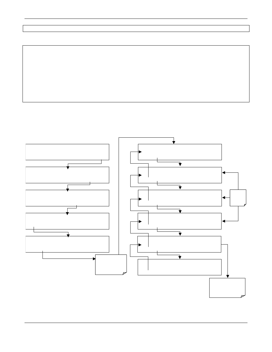
To view the above properties, press:
SAMPLE
ENTER SETUP PASS : 818
8 1 8
ENTR
EXIT
SETUP X.X
PRIMARY SETUP MENU
CFG DAS
RNGE
PASS CLK
MORE
EXIT
SAMPLE* RANGE = 500.000 PPM CO2 =X.XXX
< TST TST > CAL
SETUP
SETUP X.X
COMMUNICATIONS MENU
ID
INET
COM1
EXIT
SETUP X.X
SECONDARY SETUP MENU
COMM
VARS DIAG ALRM
EXIT
SETUP X.X
DHCP: ON
SET>
EDIT
EXIT
SETUP X.X
INST IP: 0.0.0.0
EXIT
SETUP X.X
GATEWAY IP: 0.0.0.0
EXIT
SETUP X.X
SUBNET MASK: 0.0.0.0
EXIT
SETUP X.X
TCP PORT: 3000
EDIT
EXIT
SETUP X.X
HOSTNAME: M360E
EDIT
EXIT
EDIT Key
Disabled
From this point on,
EXIT returns to
COMMUNICATIONS
MENU
Don not alter unless
directed to by Teledyne
Instruments Customer
Service personnel